Contour Projectors-Keeping Up with the Times

The contour projector, also known as an optical comparator or shadowgraph, has been used for quality control inspection for more than 70 years. Despite its maturity, the projector is still around and going strong. Its lasting value comes from its versatility in today’s manufacturing environments, and its precision comes from the eye of the operator.
Although the fundamental design is essentially unchanged, the role of the projector has changed along with manufacturing technology over time. As its name implies, one of the earliest uses for the projector was the measurement of contours on a workpiece-its straight, curved or varying edges. All projectors offer a large viewing screen capable of displaying an enlarged profile image of features on the part at an exact optical magnification. This allows the magnified profile of the feature to be directly compared to a matching master profile printed on a customized chart gage that is placed over the viewing screen. The typical chart gage shows not only the nominal feature shape but also the minimum and maximum profile tolerances specified for the feature.
Contour projectors have round screens because it is easiest to make lenses that are circular and have symmetry about the optical axis through their centers. When that circular shape is magnified, it makes the most sense to project it onto a round screen. Source: Optical Gaging Products Inc.
While the projector offers a quick go/no go evaluation, providing quantitative numerical data when measuring by comparison can be difficult. The measurement process is always subjective because both the operator’s eyesight and degree of care can enter into the evaluation of the part. With the advent of digital position readout systems (DROs) for the projector’s table motion, the primary tasks that projectors perform today have slowly changed from full screen measurement by comparison, to measurement by translation relative only to the screen centerline.
Random flaws and indistinct, variable features are difficult to program on an automatic video system, but can be easily accomplished with a contour projector. Source: Optical Gaging Products Inc.
Video Measuring Systems
Today nearly every projector manufacturer also offers several models of automatic video inspection equipment. Modern video measuring systems use solid-state cameras to electronically evaluate optical images projected into the camera. Computers are programmed to analyze the camera images for the location and size of preselected features on the part as they are brought into view. The system’s software detects edges automatically and evaluates preselected feature size and location numerically. When nominal values and tolerances for the feature are supplied, deviations from nominal and out-of-tolerance conditions can be generated automatically. Computer numerical control (CNC) video measuring machines can automate inspections and eliminate operator variability.If video measuring systems work quickly and automatically and provide numerical evaluations of features on the part without subjective human intervention, why use a projector? This is where the projector’s versatility comes into play. Examples of some inspection tasks better performed on a contour projector than another piece of equipment follow.

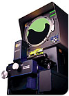
The projector images the magnified view of the part directly onto a large frosted screen. Source: Optical Gaging Products Inc.
Making it Easier with a Projector
Measurement by comparison of parts that fit within the field of view with a chart gage is fast and easy. The eye is excellent at determining parallelism and spacing when aligning a chart gage and a part.There is an important technical consideration when measuring by comparison. Since this measurement utilizes the entire screen area, it requires accurate, distortion-free images across the full screen. High-quality optics and illumination sources play critical roles in making effective measurements with this technique.
Precision assembly and manual alignment of miniature components is easier on a projector because orientation and adjustment is more easily performed when the operator can see a large area on the viewing screen. A field of view of 3 inches is available on the projector at 10 times the magnification with a 30-inch, diameter-viewing screen. An entire 3-inch workpiece magnified 10 times in a single scene on the screen makes position and alignment easy to see. Projectors with a horizontal viewing axis are particularly convenient to use for tasks requiring a lot of manual manipulation because the operator is positioned directly in front of the screen with the assembly easily at hand on the worktable.
The video measuring system images the part onto a solid-state detector that is typically smaller than 1 inch across and contains numerous, individual pixels. The electrical signals of all the pixels, corresponding to different light levels, are analyzed by software to determine feature locations and presented onto a video monitor. Source: Optical Gaging Products Inc.
An example of newer technology applied to projectors is the use of digital rotary encoders that make angle measurements even easier. The procedure is the same, but the angles are digitally displayed in 0.01-degree increments on a DRO. The alternative procedure on a video measuring machine or CMM requires acquiring points along each side of the angle, then fitting and intersecting those lines to get the angle.
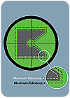
This illustration shows measurement by comparison with minimum and maximum profile tolerances. The shadow of the part is within the minimum and maximum profile tolerances as shown by the dashed lines. Source: Optical Gaging Products Inc.
Projectors offer a means to evaluate subtle characteristics in an image such as color, texture or roughness. These subjective evaluations can be done by comparing the part against a known standard part or, with experience, by making the required evaluations directly based on selected characteristics in the image.
Tasks such as inspection for flaws and measuring features that are indistinct because of roughness, dirt, low contrast or poor focus often are accomplished easily with projectors. Finding a burr can be a side benefit during any inspection. Random flaws and indistinct, variable features are difficult to program on an automatic video system and essentially impossible on a CMM.
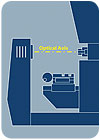
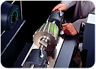
In a horizontal projector, the optical imaging axis is parallel to the floor. At normal working height the front of the part faces the operator so he sees the part and its image at the same time. Source: Optical Gaging Products Inc.
Projecting into the Future
It is true that the modern projector can have electronic edge detection located at the center of the viewing screen that will detect high-contrast, backlit edges. The projector also may have a digital position display for the table movement with geometric feature computation functions built in. While these capabilities can significantly extend the projector’s usefulness, the projector is still not as capable of full automation as the modern video inspection system.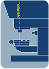
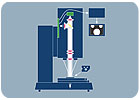
A vertical projector faces downward at the part so its surface is parallel to the floor. The part surface and the image are perpendicular to one another. Source: Optical Gaging Products Inc.
Projectors and video measuring systems will continue to co-exist because each is good at what it does. When and where each system is used depends on what the operator needs, and how fast and often he needs it. In any case, it is a safe bet that the big round projector screens will continue to be seen in manufacturing operations everywhere. Q
Quality Online
For more information on projectors and optical comparators, visit www.qualitymag.com to read these articles:Tech Tips
Measurement by Translation
Before moving worktables were incorporated into projectors, special slide fixtures with accompanying chart gages were used to measure long parts that did not fit within the field of view. Eventually, micrometer heads were incorporated into worktables to track changes in position. Higher end projectors now use glass scales integrated into a geometric processor with a DRO for making measurements.There are two main advantages to measuring by translation. First, because part features are measured at the screen centerline, there is no need to image the entire part at once. This means that large parts that cannot be imaged all at once can be measured easily-no matter the size of the projector. Second, projectors can operate in computer numerical control (CNC) mode when worktables are combined with motor drives, edge detection and automation software. This significantly increases productivity and reduces operator subjectivity. In order to measure accurately using worktable motion, optical stability and mechanical accuracy are paramount. In addition, when measuring in CNC mode, edge detection must be repeatable.
Appropriate Screen Size and Magnification
Projectors range from small benchtop units to floor models with screens of 30-inch diameters or more. Lenses from 5X to 100X are typically available. The field of view, or size of the area being magnified, equals the screen diameter divided by the lens magnification. Here is the calculation for a 20X lens on a 20-inch projector:20" = 1"
-
20
This means that 1 inch of the part will fill the screen at 20 inches. Therefore, a feature that is 0.01 inch will image as 0.2 inch on the screen. That same lens on a 30-inch projector will image an area of 1.5 inches on the part.
Projectors make it easy to satisfy the 10:1 rule for measurement. Use a 10X lens and the image is 10 times larger than the field of view. Quick-change lens mechanisms make it easy to use different magnifications on a projector allowing different levels of resolution for a particular inspection, or different magnifications per part.
Looking for a reprint of this article?
From high-res PDFs to custom plaques, order your copy today!


