Take a Closer Look at Ultrasonic Inspection
In the context of ultrasonic inspection, contour following is a scanner’s ability to do a controlled displacement of one or multiple axes.

The introduction of automated ultrasonic inspections has benefited the nondestructive testing (NDT) field in terms of imaging capabilities, repeatability of inspection data and speed. Ultrasonic immersion tanks and squirter systems are now widely used for flaw detection in aerospace components, while portable automated systems are mounted to structures for corrosion mapping. In either case, reliable inspections must be accomplished in order to benefit from the automation of the process.
One of the important requirements of reliable ultrasonic inspections is to maintain a constant ultrasonic beam entry angle throughout the whole inspection; a 0-degree inspection requires that the waves enter the test piece at 0 degrees all the time.
Another parameter that needs to be controlled adequately is the distance between the transducer and the part, or the delay line or water path. This is equally true to obtain a consistent focus depth with focused transducers as it is to remain out of the near-field zone of flat transducers or to use a distance amplitude correction (DAC) curve.
Most of the components inspected with ultrasonic immersion or squirter systems have simple geometries (flat or cylindrical) and can be either inspected in a rectangular pattern or with the use of a turntable. Controlling the wave’s incidence angle and water path is then mostly related to the mechanical alignment between the scanner’s axes and the surface to be inspected.
 However, complex shapes that present inclined, curved or multiple surfaces require more advanced scanning schemes in order to be inspected properly. Three options are then available: scanning the part in multiple passes if it is composed of multiple simple shapes, performing a manual inspection of the surfaces that cannot be done from simple scan patterns or using surface following capabilities to inspect the whole part as a single surface. The last option represents the most interesting one since it provides a controlled and repeatable way of performing the required inspections. On the other hand, its realization is the most challenging as it requires advanced scanning capabilities.
Two distinct types of surface following can be defined according to component geometry. Complex parts that do not present any axis of symmetry, such as most turbine blades, require considering a full tri-dimensional knowledge of the component in order to control the transducer orientation; three-dimensional surface following capabilities are therefore required.
On the other hand, parts that do have an axis of symmetry, such as extrusions, represent a simplified case of the latter since they can be defined as the repetition of a 2-D contour along the extrusion axis. Surface following inspection of such parts can be achieved with an axis aligned with the axis of symmetry of the specimen and a 2-D surface follower. This type of surface following is sometimes referred to as 2½-D scanning, or simply contour following.
At least one rotational axis is required to perform noncontact contour following. The linear axes serve to move the transducer at the proper locations while the rotational axis is either used to maintain the proper ultrasonic wave entry angle or to rotate the part.
In either case, coordinates and orientation (normal vectors) of points on the surface of the part must be sufficiently sampled. Locating the part within the coordinates of the axes of the scanner also is mandatory. The second methodology, which is often referred to as a Teach and Learn procedure, presents the advantage of defining the part surface, orientation and location as a whole using the ultrasonic inspection scanner itself.
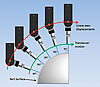
In pulse-echo, the amplitude of an echo reaches a maximum value when the ultrasonic beam hits a reflecting surface perpendicularly, meaning the reflected waves follow the same path as the incident waves. The surface orientation can therefore be obtained from the probe angle that optimizes surface echo amplitude (pulse-echo). The distance between the probe surface and the part can be estimated accurately from the time-of-flight of the echo, or water path.
It is therefore possible to measure the coordinates and orientation of multiple locations on the part surface and record them to define the contour. After a proper sampling of the desired area has been done, interpolation is performed to predict the position of the part surface between the recorded coordinates and to calculate a valid trajectory for the scanner’s axes. Since the end objective of this process is to scan at constant water path and incidence angle, their desired values must be considered in the path calculations.
A visualization of the part contour definition progress is desirable as a first visual confirmation of its accuracy. Since the optimization of the echo amplitude requires displaying the A-Scan, it is preferable to display all of this information simultaneously. Contour following is therefore better suited by a dual monitor display: a first monitor for the A-Scan visualization software and a second one for the contour following part definition.

While water path deviations can be monitored from the time-of-flight of surface echoes, validating the incidence angle requires an indirect measurement. Setting a tolerance on the amplitude variations of the surface echo recorded at 0-degree incidence represents an efficient way of monitoring errors in the surface contour orientation; a large variation in the amplitude of the surface echo may indicate that the incidence angle at that location is not 0 degrees. If either alarm is triggered, a verification of the incidence angle can be done at the problematic locations and surface coordinates can be added or modified to increase the part definition accuracy.
After the part contour has been defined and validated, contour following algorithms can be used to calculate axes trajectory covering the complete part contour without risks of collisions. One of the possibilities offered by contour following is the ability to perform angle beam inspection while following the contour. After the part contour has been defined, the inspection path can be calculated to account for a specific incidence angle on any point of the structure.<
A complete ultrasonic coverage of the inspected part implies that the contour follower provides a means of performing the inspection with a constant increment on the part surface or, in some situations, at a certain depth within the material. The simplest and most direct way of representing inspection data is to unroll the curved part, representing it as a flat component. All points scanned along the part contour are then displayed side by side and since a constant scanning step is provided, conventional rectangular C-Scans and associated B-Scan views can be built from simple gates covering a given depth range below the surface.
In addition, because all A-Scans are acquired with identical water path and entry angle, defect detection can be achieved with DAC curves. However, the inspection of identical defects below surfaces of different curvatures requires different DAC curves. This is highlighted here where different amplitude vs. depth patterns are observed between flat and curved sections, particularly where the echo amplitude decreases more rapidly with depth. DAC curves can therefore be drawn provided that a properly conceived calibration block presenting the same curvatures as the parts to be inspected is used.
A contour following procedure based on an ultrasonic definition of the part contour should now be clear. The example of a calibration block manufactured for contour following training explained process as well as how to interpret resulting B and C-Scans.
By respecting the mandatory conditions of constant water path and incidence angle, C-Scans can be generated from simple gates and DAC curves can be used for defect detection. NDT

Contour following is a scanner’s ability to do a controlled displacement of one or multiple axes, with the objective to move around a round, curved or inclined surface with constant transducer orientation and distance.
When contact inspection is performed, this can be relatively well achieved by a spring loaded swiveling head as long as the part surface does not present large variations.
When it comes to performing an inspection with an immersion or squirter system, the orientation of the transducer must be precisely controlled in order to follow the part contour adequately.
Positioning of a point on the part surface in the set of coordinates of the scanner’s axes can be achieved using the actual probe coordinates and orientation and the water path of an optimized echo. Source: TecScan Systems
The introduction of automated ultrasonic inspections has benefited the nondestructive testing (NDT) field in terms of imaging capabilities, repeatability of inspection data and speed. Ultrasonic immersion tanks and squirter systems are now widely used for flaw detection in aerospace components, while portable automated systems are mounted to structures for corrosion mapping. In either case, reliable inspections must be accomplished in order to benefit from the automation of the process.
One of the important requirements of reliable ultrasonic inspections is to maintain a constant ultrasonic beam entry angle throughout the whole inspection; a 0-degree inspection requires that the waves enter the test piece at 0 degrees all the time.
Another parameter that needs to be controlled adequately is the distance between the transducer and the part, or the delay line or water path. This is equally true to obtain a consistent focus depth with focused transducers as it is to remain out of the near-field zone of flat transducers or to use a distance amplitude correction (DAC) curve.
Most of the components inspected with ultrasonic immersion or squirter systems have simple geometries (flat or cylindrical) and can be either inspected in a rectangular pattern or with the use of a turntable. Controlling the wave’s incidence angle and water path is then mostly related to the mechanical alignment between the scanner’s axes and the surface to be inspected.
Contour following using a spring-loaded swiveling head in contact with the part is limited to small curvatures. Source: TecScan SystemsSource: TecScan Systems
Two distinct types of surface following can be defined according to component geometry. Complex parts that do not present any axis of symmetry, such as most turbine blades, require considering a full tri-dimensional knowledge of the component in order to control the transducer orientation; three-dimensional surface following capabilities are therefore required.
On the other hand, parts that do have an axis of symmetry, such as extrusions, represent a simplified case of the latter since they can be defined as the repetition of a 2-D contour along the extrusion axis. Surface following inspection of such parts can be achieved with an axis aligned with the axis of symmetry of the specimen and a 2-D surface follower. This type of surface following is sometimes referred to as 2½-D scanning, or simply contour following.
The end objective of contour following is to move parallel to a part surface with constant water path and beam entry angle. This example shows a probe attached to a gimbal axis and moving in the X-Z plane. Source: TecScan Systems
What is Contour Following?
In the context of ultrasonic inspection, contour following can be described as a scanner’s ability to do a controlled displacement of one or multiple axes, with the objective to move around a round, curved or inclined surface with constant transducer orientation and distance (water path). When contact inspection is performed, this can be relatively well achieved by a spring-loaded swiveling head as long as the part surface does not present large variations. However, when it comes to performing an inspection with an immersion or squirter system, the orientation of the transducer must be controlled with a high degree of precision in order to follow the part contour adequately. Of course, this must be accomplished without any collisions between the scanning head and the inspected specimen.At least one rotational axis is required to perform noncontact contour following. The linear axes serve to move the transducer at the proper locations while the rotational axis is either used to maintain the proper ultrasonic wave entry angle or to rotate the part.
Coordinates and orientation of an element of the part surface can be measured by tuning the wave’s incidence angle until the surface echo reaches its maximum. Source: TecScan Systems
Defining a Contour Following Path
Before a contour following inspection can be completed, the displacement path of all the axes involved must be defined properly. Because the purpose of this procedure is to maintain constant water path and wave incidence angle, the surface location and shape must be known accurately before a propagation path can be defined. Methodologies that can be used to define the part surface are either to import part geometry from an external source such as a computer-aided design (CAD) file or scanning device, or to use the ultrasonic scanner to define the surface geometry point-by-point.In either case, coordinates and orientation (normal vectors) of points on the surface of the part must be sufficiently sampled. Locating the part within the coordinates of the axes of the scanner also is mandatory. The second methodology, which is often referred to as a Teach and Learn procedure, presents the advantage of defining the part surface, orientation and location as a whole using the ultrasonic inspection scanner itself.
In pulse-echo, the amplitude of an echo reaches a maximum value when the ultrasonic beam hits a reflecting surface perpendicularly, meaning the reflected waves follow the same path as the incident waves. The surface orientation can therefore be obtained from the probe angle that optimizes surface echo amplitude (pulse-echo). The distance between the probe surface and the part can be estimated accurately from the time-of-flight of the echo, or water path.
It is therefore possible to measure the coordinates and orientation of multiple locations on the part surface and record them to define the contour. After a proper sampling of the desired area has been done, interpolation is performed to predict the position of the part surface between the recorded coordinates and to calculate a valid trajectory for the scanner’s axes. Since the end objective of this process is to scan at constant water path and incidence angle, their desired values must be considered in the path calculations.
A visualization of the part contour definition progress is desirable as a first visual confirmation of its accuracy. Since the optimization of the echo amplitude requires displaying the A-Scan, it is preferable to display all of this information simultaneously. Contour following is therefore better suited by a dual monitor display: a first monitor for the A-Scan visualization software and a second one for the contour following part definition.
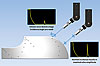
Contour Following. This calibration block is designed for contour following training with groups of SDH machined at 0.25, 0.5, 0.75, 1.25 and 1.75 inches below the surface. The block is separated in five sections of different curvatures: three flat and two curved. Dotted lines indicate transitions between sections. Source: TecScan Systems
Validating the Contour Following Path
An important step in the definition of the part contour is the validation of the scanner’s displacement path in the interpolated areas, which can be done by comparing the deviation of the water path and incidence angle with regards to an acceptable error. While moving around the contour, a visual alarm can be set to advise the operator of deviations beyond this acceptable error.While water path deviations can be monitored from the time-of-flight of surface echoes, validating the incidence angle requires an indirect measurement. Setting a tolerance on the amplitude variations of the surface echo recorded at 0-degree incidence represents an efficient way of monitoring errors in the surface contour orientation; a large variation in the amplitude of the surface echo may indicate that the incidence angle at that location is not 0 degrees. If either alarm is triggered, a verification of the incidence angle can be done at the problematic locations and surface coordinates can be added or modified to increase the part definition accuracy.
After the part contour has been defined and validated, contour following algorithms can be used to calculate axes trajectory covering the complete part contour without risks of collisions. One of the possibilities offered by contour following is the ability to perform angle beam inspection while following the contour. After the part contour has been defined, the inspection path can be calculated to account for a specific incidence angle on any point of the structure.<
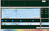
The results obtained from the contour following inspection of the calibration block are shown: C-Scan of the SDH and B-Scans at the cursor position (enhanced contrast). Transitions between curved sections are indicated by dotted lines; some SDH of sections 3 and 4 are seen from both sections. Source: TecScan Systems
Contour Following Inspection
Here we will examine contour following inspection for an aluminum calibration block specifically designed for training purposes (see “Contour Following” figure). Its shape integrates flat, concave and convex surfaces, as well as sharp corner angles, where groups of five side-drilled holes (SDH) were machined at identical depths for all surface types. When inspecting this block with contour following, SDH should be detected at the prescribed depths for all curvatures. A 10 megahertz focused transducer with a diameter of 0.25 inch was used in this example.A complete ultrasonic coverage of the inspected part implies that the contour follower provides a means of performing the inspection with a constant increment on the part surface or, in some situations, at a certain depth within the material. The simplest and most direct way of representing inspection data is to unroll the curved part, representing it as a flat component. All points scanned along the part contour are then displayed side by side and since a constant scanning step is provided, conventional rectangular C-Scans and associated B-Scan views can be built from simple gates covering a given depth range below the surface.
In addition, because all A-Scans are acquired with identical water path and entry angle, defect detection can be achieved with DAC curves. However, the inspection of identical defects below surfaces of different curvatures requires different DAC curves. This is highlighted here where different amplitude vs. depth patterns are observed between flat and curved sections, particularly where the echo amplitude decreases more rapidly with depth. DAC curves can therefore be drawn provided that a properly conceived calibration block presenting the same curvatures as the parts to be inspected is used.
A contour following procedure based on an ultrasonic definition of the part contour should now be clear. The example of a calibration block manufactured for contour following training explained process as well as how to interpret resulting B and C-Scans.
By respecting the mandatory conditions of constant water path and incidence angle, C-Scans can be generated from simple gates and DAC curves can be used for defect detection. NDT
Here is a representation of the expected position of the SDH in the Contour B-Scan (horizontal to vertical scale ratio is 2:1) in the unrolled view of the calibration block. Blue sections on the sides represent the sections of the sample that were not scanned. Source: TecScan Systems
Tech Tips
Looking for a reprint of this article?
From high-res PDFs to custom plaques, order your copy today!


