Three-dimensional imaging technology has been rapidly evolving as has its use in machine vision. Three-dimensional imaging is used in other fields such as object and space modeling, computer vision, R&D work or autonomous robot guidance; some of the methods used in those fields have had little or no use in machine vision. While the line between other fields and machine vision is often blurred, the emblematic differences of machine vision influence which 3-D technologies get used. These include the need to accomplish repetitive automatic inspection, robot guidance and automated image analysis tasks rapidly with near-100% reliability within reasonably well-defined scenarios.
Certain machine vision methods are able to extract limited 3-D information without actually developing the 3-D image. Examples of these are methods using structured laser illumination or systems that can determine distance from the apparent size of known objects. These are worth noting, however, and this article will highlight methods that form at least partial 3-D images.
Compared to conventional 2-D, machine vision 3-D imaging isn’t necessarily an “upgrade.” Instead, it is a different method of imaging that is more limited in some areas and more capable in others. The 3-D imaging method does not produce gray scale or color information, although conventional imaging may be added to accomplish this. Three-dimensional imaging does provide shape information of the surface of the product, and does not require lightness/darkness or color differences to create images.
As a result of these strengths and weaknesses, 3-D imaging is generally used only when it is necessary to do things that are impossible or difficult to do with conventional imaging.
The most common reason to use 3-D in machine vision is cases where it can create reliable differentiation of features or defects where such is impossible or difficult to do using conventional imaging. Differentiation requires contrast, and so the easiest applications for 2-D imaging involve identifying features that are different colors or darkness compared to what surrounds them. When such a difference does not reliably exist, more complex spatial solutions (lighting geometry etc.) can be used in 2-D vision but when such is not enough or adversely impacts feasibility, a move to 3-D is often the best choice. A few examples of 3-D imaging applications we’ve done include robot guidance, mold clearance checking, reading of “same color” raised or sunken characters and 2-D codes, assembly verification, BGA (ball grid array) inspection, human dimensioning and special-case bin picking.
As the technology develops, it is beginning to tackle applications which require and benefit from developing abilities to analyze (as well as image) in general-case three dimensions not reducible to depth maps. One example of this is evolution towards a true general case solution for bin picking applications.
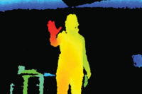
Most methods start by producing a depth map type image. For example, this may be a 2-D array of pixels (just as a conventional 2-D image) but instead of each pixel containing grayscale or RGB color values, it contains the “Z” (third) dimension information of distance of each point from the imager or imaginary viewing point. One or more depth map images can be transformed into a “point cloud,” which contains the three dimensions of each point. While a depth map is more limited in what it can represent, it does have the advantage that it can often be processed using the same machine vision tools as 2-D vision. For example, to find “bump” defects on a surface, the height might be coded as a grayscale value, areas above a certain height can be separated by thresholding, and be evaluated (based on size) against defect criteria by calculating and screening by common parameters such as area and perimeter of the defects. Similarly, raised or sunken lettering or 2-D codes can be separated from the background via thresholding, and then read via standard OCR or code reading tools.
3-D Scanning/Triangulation
This is the most often used method in machine vision. One reason for this is that it has been around the longest with respect to substantial use in machine vision.
This technology uses a laser (often IR) that scans the work piece one line at a time, and an imager that looks at each point generated. The imager and laser are located in known positions and (different) angles with respect to the product. Since the locations and angles of the imager and laser are known, this allows the processor to determine the position (in 3-D space) of each point generated. This is done for one entire line. Then, as the imaging system or product is moved in a controlled “scanning” fashion, it repeats the process for the next line and hundreds or thousands of additional lines until the required portion of the work piece has been covered. All of the data is put together into a depth map 3-D image of the scanned area of the product.
One limitation of this method (actually of all imaging methods covered in this article) is that only the area that is “seen” by two elements (in this case the laser and the camera) is imaged. A few more important limitations for this particular method are:
To create an image, either the work piece or the imaging system must be steadily and accurately moved in a scanning type motion. This usually requires adding some type of a motion control system. Also the image acquisition time includes the time for the entire scanning process which is too slow for many applications. Finally, such an addition (particularly if it involves handling and moving the work piece) is generally not allowed on “add on” solutions which must not modify the existing manufacturing and product flow process.
The system relies on scattered (not reflected) light from the laser impact point, so only products/areas that scatter light may be imaged. The shinier the object, the less this method can image it. For example, a flat-white product would be the easiest to image and a mirror would be the most difficult.
Since the image is constructed only once per scanning cycle, a “live” image (e.g. for setup and aiming) which requires about 30 images per second is not available.
Stereoscopic Imaging
Like a set of human eyes, stereoscopic imaging is based on two cameras capturing two different views of a product or “scene.” These cameras, positioned slightly apart on the same plane, take the images which are then stored in the computer. The resulting pictures are not exactly identical; the space between the two cameras means the resulting images show the same scene, but from slightly different angles. Next, the commonalities and differences between the two images are identified. The differences are known as the “disparities” in the positions of the features. It’s the disparity that communicates the depth of the image or the “3-D-ness” of it.
For humans, stereoscopic vision and its resulting depth perception is vital for actions such as driving, throwing/catching a ball, even threading a needle. It’s not that these activities can’t be done without this type of vision, but having it makes life a whole lot easier. Unlike stereoscopic machine vision, a human’s “vision” of an object comes from the mind, which combines an immense amount of other information (such knowledge of the world and common objects) with the information received from the eyes and so the analogy has its limitations.
The primary limitation of this method with respect to machine vision is that the features of interest must be visible (reliably differentiated) using conventional imaging, and the most common reason for using 3-D in machine vision is because this differentiation is not available. The other significant limitation is that the 3-D information is available only for differentiated features. These limitations are among the main reasons its use in machine vision is the least of the three methods described in this article.
“One shot” grid based 3-D imaging
A newer 3-D technology that is rapidly growing in machine vision is the “one shot” method which uses a projection of an invisible (near-IR or IR) specialized grid. It is marketed under various names. This method may be understood as starting with a configuration similar to the scanning triangulation method (emitters and a camera in known positions and angles). The difference is that it projects a specialized (e.g. pseudo-random) grid over the entire product area at one time. The imaging and processing system “knows” the origination point, transmits angle and location in the field of view of each piece of the grid. From this, it calculates its three-dimensional position and puts it into a depth map image.
The biggest advantage of this new method (compared to mature triangulation methods) is that it takes the picture of the entire scene in one shot. A controlled scanning motion of the imager or work piece (and the time and machinery for such) is not required. This significantly expands the range of applications. A live image is also available, making it easier to set up.
Two of the limitations of this method are the same as those of laser triangulation. It can only image areas that both of the elements can “see,” and requires surfaces that scatter light.
Two additional limitations of this method compared to conventional triangulation are (typically) lower accuracy and longer minimum working distances. Newer versions of this technology are making significant advances and narrowing the gap in these two areas.
Both 3-D imaging technologies and their adoption to machine vision applications continue to grow. Compared to 2-D imaging, they offer new capabilities and limitations, varying with the 3-D method being considered. Judicious decision-making based on knowledge of both is essential. The new capabilities allow ongoing expansion of the range of applications that may be solved using machine vision.
TECH TIPS:
- Three-dimensional imaging is a different method of imaging that is more limited in some areas and more capable in others.
- The 3-D imaging method does not produce gray scale or color information, although conventional imaging may be added to accomplish this.
- Today 3-D imaging is generally used only when it is necessary to do things that are impossible or difficult to do with conventional imaging.


