The science and technology of 3-D measurement has evolved dramatically in recent decades. Accordingly, a wide range of industries continue to adopt 3-D scanning as a key tool for ensuring optimal quality of manufactured goods, reverse engineering and other related processes. And many more advantageous uses remain unexplored.
Obtaining precise 3-D dimensions of an object enables its rapid reproduction and redesign. The same data can be used to perform quality control and inspection analysis for a fast “go/no go” decision in manufacturing.
Let’s review a few 3-D measurement basics for those who may be considering using this technology.
When you decide you have a need to 3-D measure a part or product, the first step is to contact a reputable engineering service provider who will scan the object, obtain its measurement data, and provide you with a workable CAD file. Some questions to ask potential service providers: How many years have they been in business? What services do they provide beyond gathering the measurement data? What type of equipment do they have? How many similar projects have they handled?
One way you can make the quoting process easier is by considering in advance what information the service provider will need in order to evaluate the job and produce a fair quote. For example, we often get emails that say, “I have three parts. How much to reverse engineer them?” We have no idea. Without pictures or approximations, we don’t know the size and shape of the parts and can’t estimate the time needed to scan and convert them into CAD models. To expedite the quoting process, provide pictures of the part along with some rough measurements so the service provider at least knows the basic dimensions of the part.
Some other things to consider before seeking quotes: How accurate does the scan need to be? Can you provide a statement of work or define how the CAD model will be used? Why are you reverse engineering the part? What file format do you want the service provider to produce? Will the model need to be easily modified? Will a neutral “dumb” solid model be enough or do you need a true parametric model? (More about these models later.) All these things impact the time and technology needed to measure your part(s) and determining them ahead of time should make the quoting experience easier for both you and the service provider.
Once you’ve contracted the job, the 3-D measurement process will consist of four basic steps: 1) Collecting the measurement data, 2) Processing the data, 3) Modeling the data, and 4) Validating the data.
Collecting the 3-D Measurement Data
In the past, parts were traditionally measured using hand tools such as calipers and tape measures, a process largely rendered obsolete by today’s 3-D scanning technology, which outstrips manual measurement both in speed and accuracy. Your service provider will likely use a 3-D scanner of some type to obtain your 3-D measurement data. A 3-D scanner examines physical objects (for example, turbine blades or automotive components) and collects data on their shape and size. As it scans an object, the scanner creates a “point cloud” of geometric samples from the object’s surface, which define its various surface shapes, contours and dimensions. The point cloud can then be converted to a CAD-friendly format to create a 3-D replication of the object.
3-D scanners can be contact or noncontact and stationary or portable. You will likely want to opt for a noncontact scanner if the product you’re measuring is fragile or prone to damage, or if its shape might be altered by contact, as in the case of soft or compressible objects.
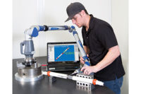
Similarly, whether you should use a stationary or portable scanner depends on what is being scanned. A stationary scanner, such as a stationary coordinate measuring machine, or CMM, is versatile and capable of capturing 3-D geometry from objects of various sizes. It also requires that you bring the object to it to be scanned. This can cause production bottlenecking if you’re measuring equipment that will need to be removed from the line to be scanned. To avoid possible delays, a portable scanner, which can scan the equipment at its current location, may be your best bet. If production bottlenecking is not a factor and your object has a relatively simple geometric shape (CMMs are slow relative to other scanning technologies), then you may want to consider using a CMM for 3-D measurement.
What if your part has a more complicated geometry? When the parts become more complex, with an abstract shape, or the entire surface area of an object needs to be measured, then the use of a high-speed, noncontact 3-D scanner should be considered. A 3-D scanner can capture the geometry and critical dimensions of a large and/or complex object in a shorter period of time, and with greater accuracy, than either a CMM or hand tool.
Here are a few noncontact 3-D scanning technologies and what they offer:
Structured Light Scanning uses white or blue light to create a series of reference patterns on an object. With each shot at different angles to the object being measured, the scanner captures data points in greater density and then stitches the different patches together, usually with pre-mounted stickers. Since the data points are denser and closer together, the object’s geometry is captured in greater detail. To stitch together multiple scans, reference stickers are often used or photogrammetry is employed. This type of scanning is a good choice for measuring intricate, detailed parts. The one negative is removal of all the stickers from the object when scanning is completed.
Computed Tomography (CT) scanning utilizes X-rays to produce 3-D representations of both internal and external surfaces. It is fast, accurate, non-invasive and nondestructive. Its ability to capture internal geometry makes CT scanning a good choice when measurement requirements exceed the capabilities of line of sight scanning technology.
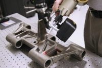
Handheld laser scanning involves a portable, noncontact laser scanning device. Whether attached to a mechanical arm or held by the operator, a handheld scanner can capture an object’s 3-D coordinates, or data points, rapidly and with a high degree of resolution and accuracy. It uses a laser stripe sensor, mounted on a portable localizer to capture lines of points as it sweeps across the surface. This quickly builds into a cloud of points defining the complete surface of the object being scanned. One advantage to these scanners is their versatility—a handheld scanner is capable of capturing 3-D measurements from objects of almost any size or shape in almost any environment. Its flexibility, speed, ease of use, and portability make it a suitable choice for nearly every type of 3-D measurement application, from consumer goods to full size automobiles.
Whatever the method used to collect the 3-D data, the goal is the same: to obtain, as accurately as possible, the raw measurement data of the object being scanned.
Processing the Data
Once your object has been scanned, your service provider will have a point cloud consisting of many (perhaps millions) of XYZ and IJK co-ordinates. This data will need to be converted into a form compatible with your CAD software. (Specialized reverse engineering software is required to handle point clouds of 50-500 MB.) The point cloud is converted into a triangulated STL (STereoLithography) polygonal file, in which the data is now a raw triangulated surface. This STL file is then used to create a 3-D IGES/STEP/parasolid model.
If you have native CAD, the next step is to take the model and convert it into the required CAD format. These formats include CATIA, Pro E/CREO, SolidWorks, Inventor, Unigraphics/NX, SolidEdge, and Siemens NX.
Modeling and Validating the Data
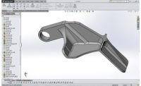
Your solid model will be constructed from the STL data by using standard tools such as extrudes, lofts, sweeps, and revolves. For more difficult components, advanced surfacing techniques may be required to achieve the desired result. Your service provider should validate the data by checking the quality of the model versus the original scan data. An accuracy analyzer can be employed to give a color map of how close the model is to the STL template.
A solid model allows you to see your part in real, 3-D space and view it from any angle. Most applications will require either a “dumb” solid model or a native CAD model. A “dumb” solid is a solid model without a history tree and the most common formats are IGES, STEP, or ParaSolid.
If your application requires a true parametric model (a model that is fully modifiable in CAD software), the model will need to be completed in SolidWorks, Inventor, CATIA, NX, or Pro E/CREO. A parametric model contains a full feature tree, which means that you can make changes to any feature of the model and every related dimension will update accordingly.
With its ability to yield better designs, recreate legacy parts, and provide an accurate basis for detailed analysis of components and processes, 3-D measurement is a key technology for engineers throughout industry tasked with saving time and improving quality.


