3D Measurement: A Next Generation Tool for Manufacturing
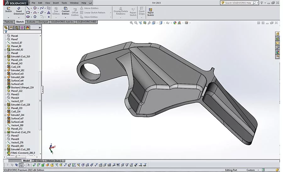
Shown here is the model fully converted to native SolidWorks with full feature tree. Source: NVision
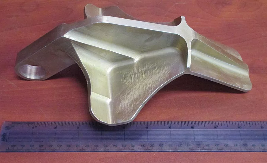
A 3D scanner can capture the geometry and critical dimensions of this part in a shorter period of time, and with greater accuracy, than traditional hand tools. Source: NVision
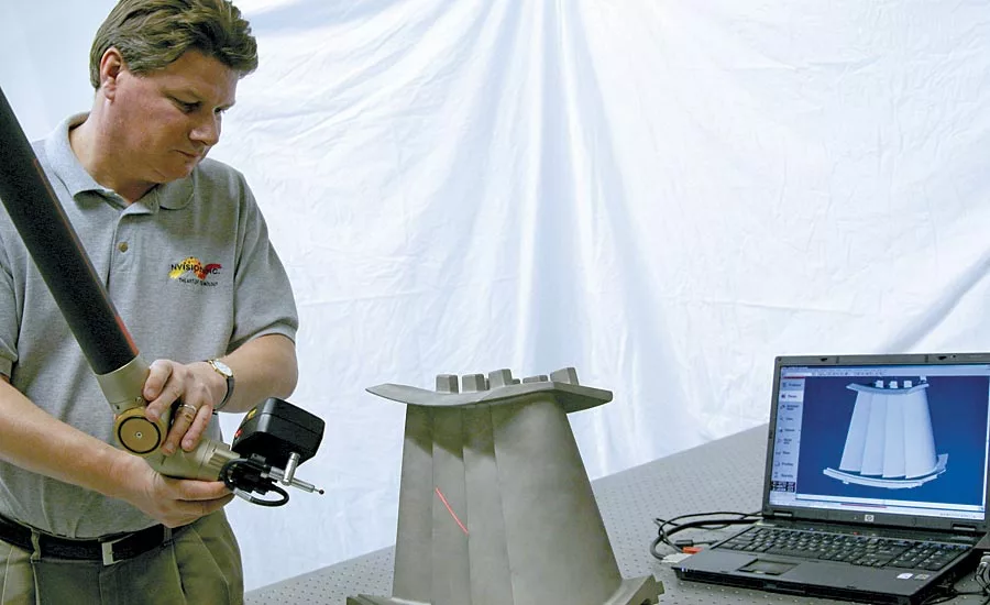
A handheld scanner, attached to a mechanical arm, scanning a nozzle. Note the red laser line on the assembly. Source: NVision
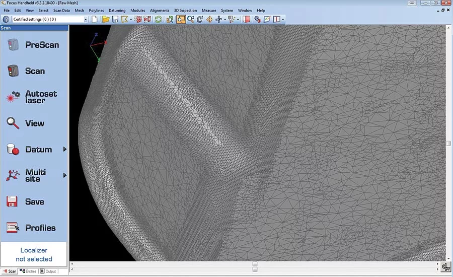
The data obtained from scanning will be converted into a triangulated STL polygonal file, which will be used as a template for modelling. Source: NVision
It’s easy to take many of today’s technological marvels for granted, 3D measurement among them. The idea of simply pointing a “ray gun” of sorts at an object and obtaining all of its geometrical measurements would once have been solely the domain of Star Trek-ian science fiction. But that, in essence, is what collecting 3D measurement data is: directing light or radiation at an object and capturing all of the essential measurements necessary to recreate or redesign it. It’s an amazing technology that has redefined quality in manufacturing and become an essential tool in gaining and maintaining a competitive advantage in industry. Obtaining the detailed 3D dimensions of an object enables its rapid reproduction and redesign. The same data can also be used to perform quality control and inspection analysis for a quick “go/no go” decision in manufacturing. With the ongoing rush to introduce new product designs at an ever-faster pace, with components growing more elaborate and complicated, it seems certain that the 21st century will see 3D measurement embraced as an essential manufacturing technology.
Your need for 3D measurement is directly proportional to the complexity of your object’s shape. When the shape of a part is simple, then calipers and other hand tools can likely be used to measure its dimensions. As a part’s shape becomes more complex, however, noncontact scanning methods become a far superior measuring method due to their ability to capture the measurements of intricate features and dimensions with an accuracy—from 0.0002 inches / 0.005 mm—far exceeding that of manual measurement techniques.
There are three main phases of 3D measurement: collecting the data, processing the data, and, finally, using the data to create a model.
Collecting the Data
As it scans an object, a scanner creates a “point cloud” of geometric entities from the object’s surface using XYZ and IJK coordinates. This data defines the object’s surface shapes, contours and dimensions. The point cloud can then be converted to a CAD-friendly format to create a 3D replication of the object for measurement, reverse engineering, inspection, rapid prototyping or mass production.
There are several different types of scanners available for 3D measurement—the one you’ll use will depend on the object you’re measuring and the type of measurement data you want to obtain. Here is a quick look at some of the noncontact scanners available:
Optical CMM scanning: A coordinate measuring machine (CMM) uses a laser or light-based triangulation sensor on the CMM to capture an object’s 3D coordinates. These systems are ideal for applications requiring extremely high accuracy such as turbine blades, injection molds, test equipment, and master gages. These systems provide higher resolution and higher accuracy than the majority of noncontact systems.
Portable CMM/Handheld scanners: These are a good choice for nearly every type of 3D measurement because of their portability, speed, ease of use, and overall versatility. They can capture 3D measurements from objects of all sizes and shapes—from boat propellers to full-size automobiles—and in almost all environments, onsite and offsite. Portable CMM scanners use a laser stripe sensor, mounted on arm based localizer, to captures lines of data points as they sweep across the object’s surface. Handheld scanners not attached to an arm require placement of stickers on the part to create a reference system between each scan. Typically, scanners attached to the arms are more accurate.
Structured Light Scanners: These scanners are an excellent choice for measuring intricate, detailed parts. They employ blue or white light to create a series of reference patterns on an object. The light deflects onto the object’s surface and the scanner captures these images to calculate the object’s depth and surface information. The data points can be captured in object-specific density and the different scanned patches are “stitched” together, usually with pre-mounted stickers. The one downside is that the stickers may need to be removed after scanning, which can be time-consuming. (This would also apply to handheld scanners not attached to an arm.)
Computed Tomography (CT): These scanners are fast, accurate, and able to capture internal geometry, making CT a good choice for 1) Measuring medical devices and other objects with internal components, and 2) Measurement requirements that exceed the capabilities of line-of-sight scanning. CT is also non-invasive, using X-rays to produce 3D representations of internal and external surfaces. Parts scanned using CT are typically smaller than one cubic foot and accuracy is dependent upon material density. Plastic and aluminum are ideal candidates for this method.
Processing the Data
Once the data collection (that is, the scanning process) is complete, your point cloud will consist of possibly millions of XYZ and IJK coordinates. Before all of this measurement data can be used for reverse engineering, inspection, etc., it needs to be converted into a form compatible with your CAD software. This is accomplished by converting it into a triangulated STL polygonal file, a process that usually involves several stages. The measurement data will also be aligned to a defined coordinate system before it’s ready for the next stage. The resulting STL polygonal model will be used as a template for processing. Commercial software specialized in handling large STL files will process the data to a finished CAD model format.
Modeling the data
A solid model will be created from the STL data by using standard tools such as extrudes, lofts, sweeps, and revolves. (A solid model allows you to see your part in real, 3D space and view it from any angle.) In dedicated reverse engineering software, a model may be created in three different ways: fully parametric for conversion to native CAD, design intent with CAD neutral output, or as a “dumb” solid model otherwise known as a “quick surface.”
A fully parametric model can be changed at any point in its structure, with the change rippling through the design to automatically modify any interdependent geometry. Once converted into a native CAD, it will have the properties of a blank screen model in software such as SolidWorks, Inventor, NX, CATIA, or PRO E/Creo. A design intent CAD neutral is built exactly like a fully parametric model without the final conversion to native CAD and is output as CAD neutral IGES, STEP, or ParaSolid. A “dumb solid /quick surface” model is a random patchwork of surfaces best fit to the STL model and output as IGES, STEP, or ParaSolid.
3D measurement provides an opportunity for excellence that was unavailable to earlier generations of industry. The ability to scan and create a precise, 3D replica of an object, complete with all its complex surface twists and turns, can still seem futuristic. But the technology is here and ready to be used by all manufacturers eager to push their quality standards beyond the next frontier.
Looking for a reprint of this article?
From high-res PDFs to custom plaques, order your copy today!


