Controlling the Dimensional Quality of the World’s Largest Tokamak
Meet the prototype for future energy production across the globe.
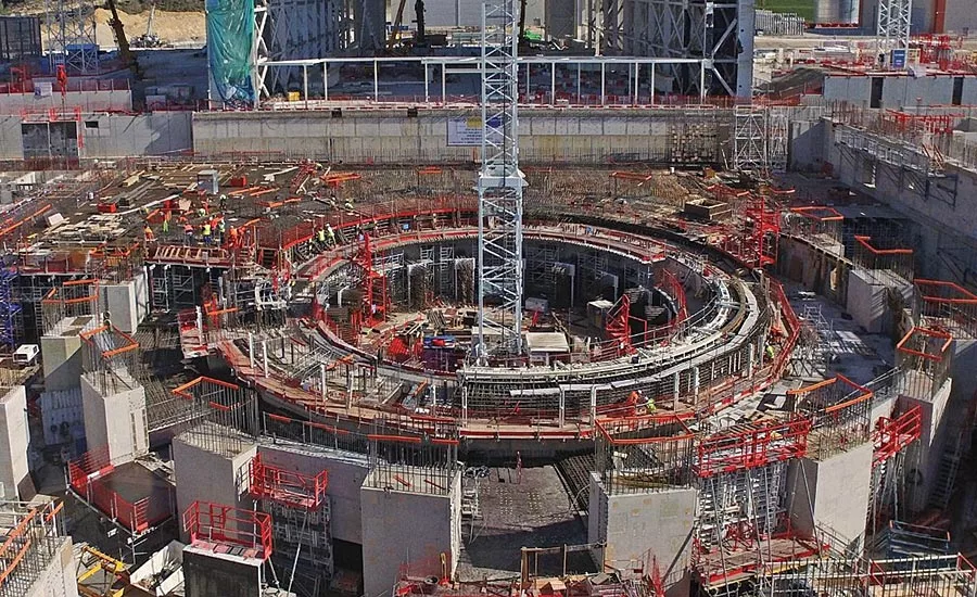
Construction continues at ITER’s site in Cadarache, France. Source: www.ITER.org
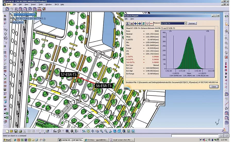
An example of Monte Carlo simulation results for an impact study. Source: www.ITER.org
An example of Monte Carlo simulation results for an impact study. Source: www.ITER.org
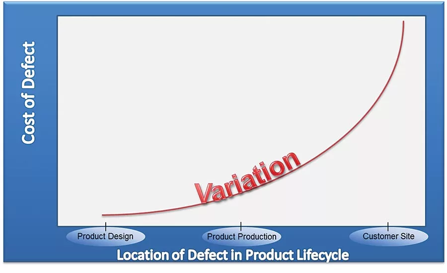
Cost to Correct Defects Across the Product Lifecycle. Source: www.ITER.org
It’s not every day that a company specializing in software solutions for tolerance analysis gets to supply an international project to build the world’s largest tokamak. But that’s what Troy, Michigan’s Dimensional Control Systems has been doing. The goal of the ITER (International Thermonuclear Experimental Reactor) tokamak project is to advance the science of fusion energy and explore its capabilities for future commercial use. The project members – China, the European Union, India, Japan, Korea, Russia and the United States – have collaborated to assemble the largest tokamak ever constructed, a prototype for future energy production across the globe. As designs evolve into the building of the machine and housing complex, there is a need for tools that analyze and predict assembly variation based on component tolerance, piece part geometry, and locating schemes.
What exactly is a tokamak? The name derives from a Russian acronym for “toroidal chamber with magnetic coils.” The tokamak was developed by Soviet research in the 1960s. It is a doughnut-shaped vacuum chamber that uses the process of fusion to produce energy. This is the same process by which the stars and sun produce heat and light. Hydrogen nuclei collide in the heat and gravity of those bodies, fuse into helium atoms and release tremendous amounts of energy. Within a tokamak, reactions of hydrogen isotopes deuterium and tritium under extreme heat (150,000,000° Celsius, 10 times the temperature of the sun) produce plasma that is maintained at the necessary temperatures and structured by magnetic fields. These fields are a toroidal field generated by external coils surrounding the vessel, a helicoidal field generated by the plasma flow around the torus center and a poloidal field that fixes the position of the plasma flow away from the chamber walls. It is this concept of magnetic confinement that defines the machine as a tokamak.
The plasma flow of a tokamak is used to generate the encircling magnetic field, but it also provides effective initial heating of the plasma. The energy produced through the fusion of atoms is absorbed as heat in the walls of the vessel. A fusion power plant can use this heat to produce steam and then electricity by way of turbines and generators. The energy produced by a tokamak is both clean and safe – there are no carbon emissions and no air pollution, and the tokamak will not explode nor leak dangerous by-products. It can be shut down safely and with far less radioactive waste than a nuclear fission plant. A major goal of the ITER project is to build a tokamak large enough to produce net energy, that is, more energy is produced by the fusion plasma pulse than is required to power the machine’s systems. The ITER tokamak and auxiliary buildings are currently under construction at the Cadarache research center in southern France (Saint-Paul-lès-Durance), with the date to begin fusion operations to be determined.
Dimensional Quality Management
Tolerance analysis has traditionally been conducted using root mean squared (RMS) of contributing tolerances on a two-dimensional plane. This stack-up analysis works well for basic assemblies; however, in large and complex structures such as the ITER Tokamak, tolerance analysis proves to be a very complex process.
The 3-D dimensional studies for the ITER system were developed and performed by the Design Integration Team within the ITER organization using 3DCS software from Dimensional Control Systems. The purpose of the dimensional analysis was to create a 3-D CAD simulation model in order to accomplish the following quality goals:
- Identification of risk issues based on non-compliant scenarios.
- Quantification of probability of occurrence of risk issues based on Monte Carlo simulations.
- Identification and assessment of mitigation strategies and customization logic, based on main contributors: part tolerances, assembly processes and compensator performance.
- Cost effectively manage tolerances and optimize processes during the construction phase.
The ITER tokamak will be the largest tokamak ever built, and proper assembly is paramount, as the unprecedented heat and magnetic strength of the system operation and fusion reaction will cause extreme stress to the machine. During operation, forces inherent to the tokamak will squeeze and pull parts of the structure in, closing gaps between them. Those gaps must be precise enough to uniformly close, leaving the parts to be largely self-supporting after steady-state operation is reached.
Creating the Variation Analysis Model
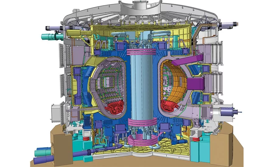
The area targeted by ITER of significant dimensional concern is the vacuum vessel portion of the plant composed of eighteen 14-meter tall “D” shaped electromagnets, called Toroidal Field Coils, which resemble an orange with nine slices. Each of these slices (or sectors) demands extremely strict tolerances (+/- 0.5 mm) to minimize custom machining and welding for successful assembly and to self-support upon activation of the device.
In order to simulate the build of the structure, a variation analysis model was needed. This model used the 3-D Geometry, Part Functional Tolerances and Assembly Procedures as inputs, simulating 3D stack up builds of the product in order to conduct risk mitigation and optimization of the design.
Creating the model was not a small task. The model required a variety of inputs in order to obtain accurate results from the Monte Carlo simulation, the virtual simulation of thousands of projected builds incorporating the model inputs and the resulting statistical analyses. All in all, the final tokamak tolerance model contained:
- 600 individual parts
- 15,000 points
- 2,000 part tolerances
- 760 moves (assembly processes)
- 30 functional/assembly requirements
- 6,000 measurements to verify compliance
Once completed, the model was applied to a variety of studies including impact studies to improve cost, schedule and performance issues as well as optimization studies to manage tolerance issues.
Identification of Risk Issues – Impact Studies
These studies focused on the impact of tolerances and assembly on the overall cost and performance of the device. By using measurements on the model, areas key to the function of the device were simulated and the impact on overall quality determined. As part of this study, the key contributors to the variation could be identified and solutions tested by altering the model and running additional simulations.
For example, the Vacuum Vessel and blankets require very tight, controlled tolerances. The space between the blankets and the vessel includes instrumentation cabling, coils and cooling manifolds, and therefore is very tightly packed. This space, therefore, is a critical issue in the dimensional studies to verify that all of the components will fit despite dimensional variation. Through simulation, it was determined that:
- Blankets should be alighted to the Magnetic Axis better than 10 mm
- Gap/Step between adjacent blankets should be controlled to 4 mm
- Blanket supports to the vessel should be customized for blanket nominal positioning
These impact studies not only determine the requirements of the build, but are also used to reduce costs in construction. By determining the impact of tolerances on the overall build, those tolerances with less impact can be loosened. This increase in tolerance, which is a reduction in the required quality accuracy, allows for less expensive manufacturing processes and assembly procedures. Through this method, those areas determined critical can be tested virtually and exact specifications determined, while those areas deemed non-critical can be made less expensively, reducing the overall cost.
Monte Carlo Analysis –3-D CAD Simulation
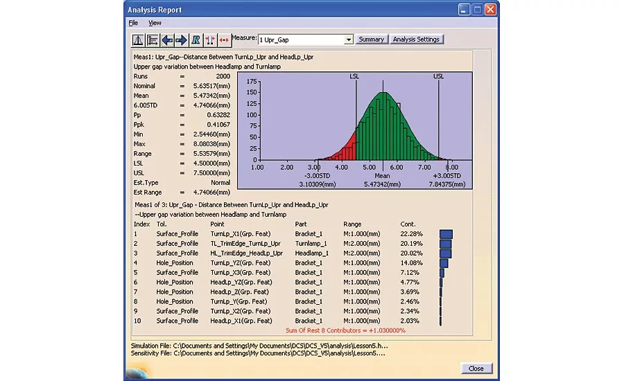
As mentioned previously, a Monte Carlo simulation virtually builds the product hundreds or thousands of times, using a standard distribution of tolerances based on the model inputs and 3-D stack up. After simulating the product builds, the simulation results are statistically analyzed, producing reports that can be used to make determinations about the design.
An example of a simulation, keyed to specific measurement placed on the model between two points, the image on the previous page highlights the kind of information that can be determined. This example shows how, given the current inputs, there will be an estimated 0% of manufactured products out of specification assuming 1,000 products are manufactured. Below the bell curve is the list of all contributing tolerances to this particular measurement, which could be a gap measurement, a flush measurement or a surface measurement, simulating how the product might be measured in a manufacturing plant setting.
By changing the inputs to the model, the results of the Monte Carlo simulation will be changed to account for the updates, allowing design of experiments and iterative studies to reduce the impact of variation.
Identification and Assessment of Mitigation Strategies
Identification of key contributors to variation on critical areas of the device drive the mitigation strategies. Contributors include both part tolerances and assembly processes and procedures. To mitigate the effect of these inputs on the overall design, different strategies may be implemented other than simply changing part tolerances. These may include:
- Updating Requirements
- Optimizing Part Tolerances based on stack up
- Optimizing Assembly
- Defining Compensators for variation
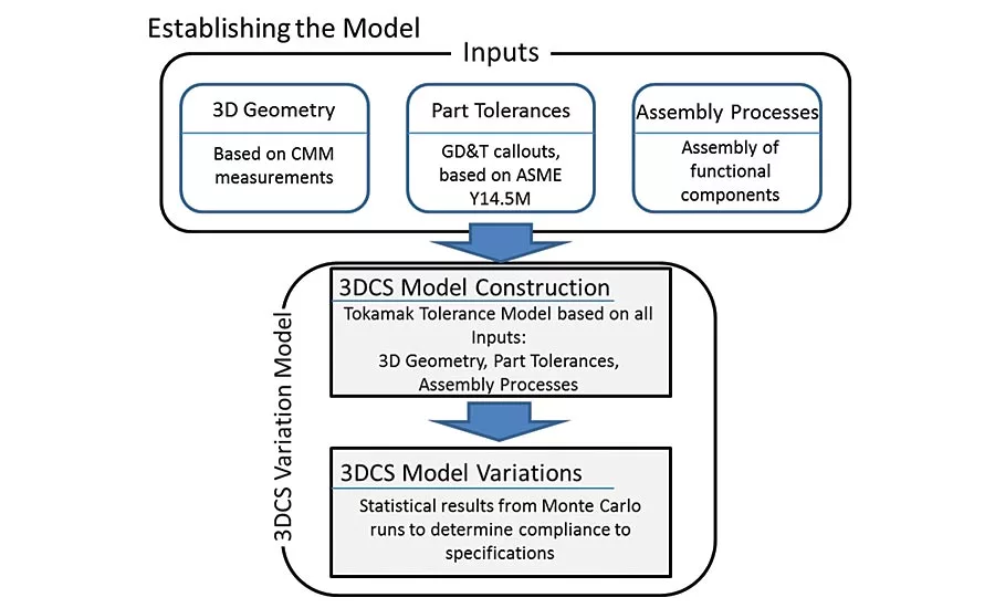
Managing Tolerances and Optimizing Processes during the Construction Phase
The key element in the simulation of the tokamak is to optimize tolerance requirements and processes before and during construction. The use of simulation studies in the design phase reduces the cost of changes that may be required for optimal functionality and assembly. The cost of defects and variation issues increases exponentially the closer to deployment. By simulating and making alterations to account for variation early in the design phase, overall quality costs can be reduced for the project as a whole.
By capitalizing on the CAD model and the specifications outlined in the production drawings, analysis can begin before the completion of the CAD model itself by using point based modeling techniques and updating the model as additional information becomes available. This gives the engineering team the ability to begin the simulation process as early in the product design phase as possible, allowing for enough time to thoroughly analyze the impacts and mitigate the risks inherent in the design.
The World’s First Production Fusion Generator
ITER aims to be the first fusion device to produce net energy. More importantly, ITER is testing the integrated technologies, materials, and physics regimes necessary for the commercial production of fusion-based electricity. This will bridge the gap between today’s smaller-scale experimental fusion devices and the fusion power plants of the future. Q
References:
Fuentes, F. Javier, Vincent Trouve, Emily Blessing, Jean-Jacques Cordier, and Jens Reich. “Status of ITER Dimensional Tolerance Studies.” Fusion Engineering and Design 88 (2013): 597-601. ScienceDirect. Web. 10 June 2016.
“ITER - the Way to New Energy.” ITER. N.p., n.d. Web. 05 July 2016.
Reese, Benjamin, Kristy Sharrow, and Thomas Halcrow. “Dimensional Control Systems” 3DCS and ITER, the World’s Largest Tokamak Experiment.” Www.3dcs.com. Dimensional Control Systems, Dec. 2012. Web.
Looking for a reprint of this article?
From high-res PDFs to custom plaques, order your copy today!


