The Application of Digital Radiography in the Aerospace Industry
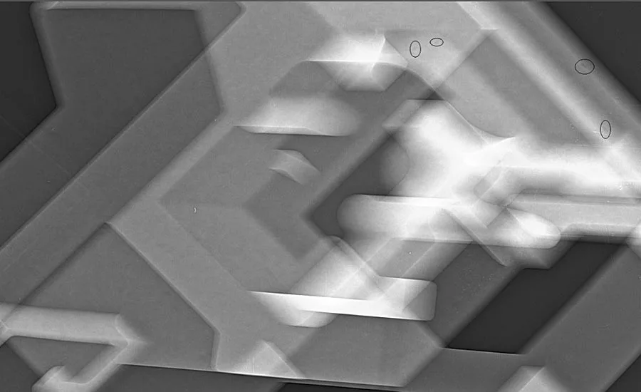
Many different parts can be tested and inspected using computed radiography.
Computed radiography, a form of X-ray imaging, has been embraced widely by many major manufacturing companies. Its application is now core for testing within a range of sectors including aerospace, oil and gas, industrial gas turbines, medical implants and prosthetics.
As a type of nondestructive testing (NDT), computed radiography is a powerful tool in the aerospace sector where it is frequently used to ensure the safety and integrity of manufactured components and assemblies.
Unlike photographic film, computed radiography (CR) scanners can be used in normal lighting conditions and stations can be set up easily alongside the X-ray unit, enabling the operator to shoot multiple exposures with minimal requirements. Imaging plates can be used directly in the hard cassette or multiple image plates via a feed tray, with up to two meter imaging plates available for panoramic exposures.
The quality of the images can be checked in real time, as they are generated and then digitally transferred and enhanced swiftly. This makes the CR technique much more efficient, through both eliminating the processing stage required for radiographic film and through the production of a much more superior quality of the final image.
Many different parts can be tested and inspected using computed radiography. Components comprising many different materials, from special alloys to composites, and through many different manufacturing methods from forgings, all types of welded parts to 3D printing (sometimes termed additive manufacturing) benefit from its use.
3D printing enables entire components to be produced directly from a 3D model and has been hailed as another important advancement in the aerospace sector. Unlike traditional manufacturing processes, 3D printing enables very complex parts to be designed and manufactured as complete units, resulting in cost savings and industry advancements through engineering technology. CR is of essential importance in verifying component structural integrity and product safety as 3D printing becomes more widely used.
Advances in Computed Radiography
A number of computed radiography manufacturers have made major improvements in digital radiography scanners, phosphor imaging plates and software applications. As a result, new products have been launched that directly meet specifications set within aerospace manufacturing and associated industries.
A number of different product types are now on the market which use cylinder or flat panel type scanners ranging from14-bit logarithmic to 16-bit linear software. Minimum pixels sizes range from 12.5µ, 25µ, 35µ, 70µ and 100µ, giving significantly improved basic spatial resolution, signal to noise ratio values and grey values to meet many of the standards now in place. These are significantly increasing the detection probability of defects in materials.
Current CR scanners and phosphor imaging plates provide scanning resolutions down to 12.5µ- 25µ (equivalent to D4/IX50 in radiographic film). These meet the sensitivity requirements in a variety of specifications, which is 2% radiographic sensitivity or better, and the probability of defect detection is now significantly higher.
System Performance Verification
System performance checks and calibrations are vitally important. User testing to ensure the long-term stability of a CR system is achieved using a CR Phantom, which is mandatory in all specifications.
The CR Phantom verifies the important performance characteristics of a CR scanner system, including basic spatial resolution (lack of sharpness), contrast, modular transfer function and detector capability, laser beam jitter, scanner slipping and scanner shading.
DICONDE is a vendor-neutral format for workflow-supporting (image) data exchange, for compliant archiving and for onscreen diagnostic reading. DICONDE files can be viewed on any DICONDE compliant equipment. DICONDE is the output of the work of the ASTM DICONDE committee (E07.11). The NDT standard (DICONDE2) is based on the medical (DICOM3) standard.
DICONDE image data written into all specifications for CR can be transferred from manufacturer to manufacturer as data is saved in raw format.
Another benefit is the ability to access the archived image date from around the world. The software storage facilities allow easy image retrieval and interpretation. Images can be downloaded and saved in just a couple of clicks. Similarly, an automatic reporting system can produce reports with images attached that can be printed or sent easily sent to customers in PDF format.
Software, Image Quality and Interpretation
Although images have to be DICONDE compliant and need to conform with SNR values set within specifications, a number of manufacturers have used complex algorithmic software to clean up screen images.
Pixelated images are notoriously difficult to interpret and poor imaging can result in discontinuities being overlooked. There’s a fine line between software enhanced images using algorithmic software and the raw data image.
In the past, some of the shortfalls of CR were due to the software that was being used to enhance images. Although onscreen images were improved, they were filtered to reduce pixilation and smooth out the image. This process can result in images being over-enhanced and filtered, meaning the discontinuities were also filtered out.
Many of the CR manufacturers have now reduced the amount of image enhancements and use more basic algorithmic software to improve visual onscreen images, bringing better interpretation and image standards.
CR manufacturers use two types of interpolation to enhance image appearance without filtering out discontinuities:
Interpolation type one = nearest neighbor: This is as close as you can get to the raw image data and only considers one pixel nearest to its closest pixel point. The image still looks slightly pixelated when you use high magnification zoom-in on the software and this is much closer to the true image, with pixilation not a problem at original IP size images or up to 4x magnification.
Interpolation type two = bilinear: This considers the closest 2x2 neighborhood of known pixel. It then takes a weighted average of these four pixels to arrive at a final interpolated value. The image is slightly smoother and less pixelated when using high magnification zoom-in on the software. This is still considered acceptable as most software used in medical radiography uses similar algorithms.
The Future of Computed Radiography
Over time, computed radiography will become more mainstream throughout the aerospace sector and has assured its place in manufacturing testing for years to come. Improvements at the lower energy range of the spectrum (0.3mm to 60mm wall castings, welds and composite materials) have been well established for a number of years. The next stage is to work at the higher energy scale (100mm-500mm wall products using 1Mev-20Mev) sourcing approvals prior to implementation.
Its environmental credentials are obvious with the elimination of chemicals associated with film processing and a reduction in chemical waste. The additional benefits of real time superior quality images and ease of file transfer between experts, allowing efficient inspection and interpretation, demonstrates computed radiography’s relevance to the sector. It has increasingly built its role as an essential tool within aerospace manufacturing, testing and inspection and is most definitely here to stay. Q
Looking for a reprint of this article?
From high-res PDFs to custom plaques, order your copy today!


