In the defense and civilian aerospace industries, wire harnesses are liberally employed in aircraft fuselages, avionics, engines, ground support equipment, and other products. To ensure proper functioning of wire harnesses, and the safety of millions of people every day, checking the quality of crimped wire terminals is of utmost importance.
Since a common expectation with wire harnesses is that their terminals do not become disconnected after final installation, simulating a mechanical failure can be quite useful. This can be done by measuring the amount of force required to remove a terminal from a wire, generally by pulling the terminal from the wire in an axial direction.
Test standards
Test standards have been developed by major agencies to cover crimped wire terminals. ISO, ASTM, SAE, NASA, MIL, DIN, BS, and other agencies specify minimum pull-off forces, measured in units of lbF, N, or kgF for given wire gages. Many of these standards require a constant pull rate to ensure consistency between tests and various operators. Although most standards are destructive in nature, by physically removing the terminal from the wire, certain other standards, such as UL486A/B, are nondestructive. This standard requires a specified force to be applied for a specified period of time. If the terminal remained crimped to the wire after this period of loadholding, the sample is considered acceptable.
Wire crimp pull testing can be performed in the following three ways, listed in order of increasing sophistication:
1. Manual testing with a force gage
A force gage is a handheld integrated instrument containing a load cell, electronics and display. Force gages are generally capable of displaying several units of measurement and capturing peak forces. Other functions, such as data outputs, pass/fail indicators, and data memory are also available. In a handheld test using a force gage, one end of the wire sample is secured to an anchor point, such as a vise. The other end of the sample is secured to a grip attached to the force gage. The user pulls by hand until the terminal is removed. The maximum pull-off force is measured and compared against a standard.
Advantages: Inexpensive, simple to configure.
Disadvantages: Limited to low force applications. Prone to variations from test to test and operator to operator because axial pull direction and test speed cannot be reliably controlled.
2. Using a lever- or handwheel-operated tester
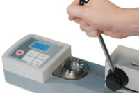
Secure the sample to a wheel- or lever-operated force tester. Some testers are integrated, with the load cell, electronics, display and grips designed into one enclosure. Or, a system can be configured from a choice of force gages, universal test stands, and grips. In any configuration, the sample is fixtured in place, thereby ensuring a consistent axial pull direction. The resulting force is compared against a standard.
Advantages: Relatively inexpensive, and sample alignment is assured. Configurable systems can be adapted to meet other force measurement applications, such as tensile, peel, and compression tests.
Disadvantages: Test speed cannot be reliably controlled, resulting in test result variation.
3. Using a motorized tester
Motorized versions of the aforementioned manual testers are available, in both integrated and configurable formats. In addition to axial alignment, motorized testers can be programmed to run at a specified speed, and certain testers can run a loadholding sequence. For specialized applications requiring an output of force vs. distance, some motorized testers are capable of distance measurement.
Advantages: Programmable speed and the loadholding function maintain test consistency, resulting in a fairer comparison of results. This test method is suggested for compliance with most standards. In addition, configurable systems can be adapted to meet other force measurement applications.
Disadvantages: Higher cost and more in-depth operator training.
Gripping the wire
Because of the wide range of force requirements, wire diameters, and terminal shapes and sizes, several grip options are available. For force gage mounting applications, grips tend to accommodate smaller wire gages and corresponding forces. They generally thread onto a force gage’s male loading shaft. For load cell and large test frame mounting applications, grips tend to accommodate larger wire gages and corresponding forces. They are generally mounted using an eye end with pin, familiar to many quality control professionals in materials testing applications. In integrated wire terminal testers, the grips are built in to the system, so mounting considerations are irrelevant.
For flag and spade terminals, the body of the terminal is typically secured against a surface with a slot for the free end of the wire. Multiple widths are generally provided, to accommodate a wide gage range. A commonly used grip is the turret-style grip, which employs a wheel with several slot widths. Other options, such as vise-action grips and wedge grips, secure the terminal by applying clamping pressure to it.
For ring terminals, a hook, clevis, or specialized pin fixture can be effective. However, this is not recommended for higher force applications, as the force may exceed the tensile strength of the ring’s material, resulting in a premature failure.
For the free end of the wire, cam and wedge grips are often effective. The self-tightening action of these mechanisms is helpful, as the wire insulation and bundle of wire strands can compress over the course of a test.
Interpreting the results
Force data can be output via USB or RS-232 to a PC or printer for tabulation and further analysis. The value of most interest to many quality control professionals is the maximum (peak) force. Other more sophisticated applications require a curve of force vs. time or force vs. distance to better analyze what’s going on behind the scenes.
If the test result is out of tolerance, appropriate corrective action is needed. Did the wires simply slip out of the terminal? Or, did the wires break at the crimping point? What other kind of failure may have occurred? The answers to these questions can help narrow down the source of the manufacturing defect, which can include the crimping tool’s settings, tensile properties of the wire and insulation materials, or the manufacturing procedure itself.
Calibration
As with most measuring instruments, periodic calibration of a force gage or force tester is important. The calibration procedure can be quite simple and quick, often doable by properly trained in-house personnel. Force measurement instruments are generally calibrated utilizing dead weights or a master load cell, usually at several points between 0 and the full scale. For large users of force measurement equipment, maintaining calibration equipment in-house can lead to significant cost savings over the long haul. Otherwise, calibration laboratories and force equipment manufacturers are available for off-site or on-site services.
Wire crimp pull testing is an important step in assuring the proper functioning of products within the aerospace industry. Since safety is of utmost importance, it is critical that component manufacturers, wire harness manufacturers, and OEMs give serious consideration to such testing to assess and ensure product quality.


