Edge Break Analysis for 3D Optical Metrology
Handheld 3D metrology that uses edge break analysis software can bring precise edge break measurements to the shop floor.
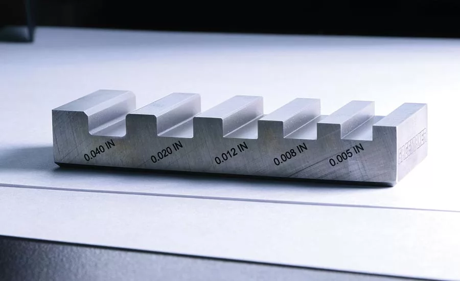
Examples of chamfers and rounded edges on an edge break standard created for edge break analysis. This standard has chamfers as well as internal and external rounded edges of varying size.
Machined parts commonly have sharp edges and corners that are “broken” for a variety of reasons in a process called edge break. Breaking an edge can be accomplished by rounding off the sharp corner, creating a rounded edge, or by machining a flat edge transition, creating a chamfer. A single machined part in the aviation and automotive industries can have dozens of edge break call outs that can be challenging and time-consuming to measure. There is a significant incentive to quickly, accurately, and conveniently measure these important callouts to speed up turnaround time and increase confidence in part geometry. To fulfill the imperatives of industry, handheld 3D metrology that uses edge break analysis software can bring speedy and precise edge break measurements to the shop floor.
Edge Break Measurement Today
Typical radius of curvature (ROC) and chamfer lengths range from around .002” (50 µm) to .05” (1270 µm). The ROC for rounded edges will ideally be consistent throughout an edge, creating a curved area between the two side planes. Chamfers will typically turn one sharp edge angle (usually a right or an acute angle) into two equal and duller obtuse angles. Manufacturers break edges because sharp corners can be the headwaters for stress fractures that spread across the part. Edges can also play a large role in fluid dynamics and therefore rigid edge break tolerances are needed to ensure proper performance of some parts. When using fasteners, chamfer geometries are tightly controlled to ensure the rivet or screw does not protrude from the part. In addition to part-longevity and performance motivations, sharp edges are a safety concern for those handling the parts and lack of proper edge breaking can lead to a significant number of workplace injuries. The importance of edge break tolerances for manufacturers leads to part drawings littered with edge break call outs to be measured.
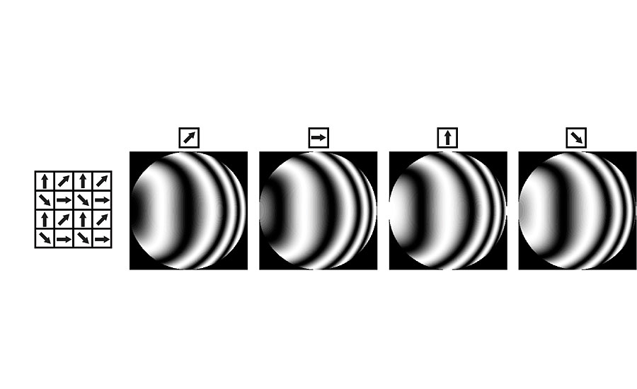
Fringes extracted for polarizers of the same angular orientation.
If you look at a shop floor today, chamfers and radii are being measured with visual tests and stylus-based systems. Visual tests are inherently subjective, depending greatly on the inspector, lighting, and alignment of the visual comparator. Most importantly, a visual test provides no quantifiable data. These methods can be quick and efficient, but they do not provide the data necessary to ensure the part is within specifications.
Perhaps the most commonly used instrument-based system for characterizing edge break geometries is the 2D stylus profiler. Any 2D measurements of edge break suffers from alignment errors and can be affected by irregularities that may be on the edge. If the 2D trace is not perfectly perpendicular to the edge, the stylus will measure the chamfer or ROC as larger than it actually is. Styli are affected by vibration and are prone to breaking when tracing over corners. Due to set-up time, measurements can take up to 30 minutes. In addition to stylus profilers, laser-based gauge guns can provide some shop-floor capability. Like the stylus profiler, these systems provide a 2D trace susceptible to alignment errors and inconsistencies in the edge. They are affected by surface finish and do not perform well on reflective materials. With lateral and vertical resolutions of tens of microns, they are not capable of measuring the fine geometries seen for edge break specifications and create a broad band of uncertainty around any given result.
Moving away from the shop floor, rubber replication materials can be used to make a facsimile of the edge and which can be sent for analysis on an optical comparator or shadowgraph. These replications can then be cross-sectioned so the ROC or chamfer length can be measured. The cross-sections fall victim to alignment errors just as the other 2D measurements do. Making the replicate, cross-sectioning it, and measuring it on an optical comparator can be a time-consuming process.
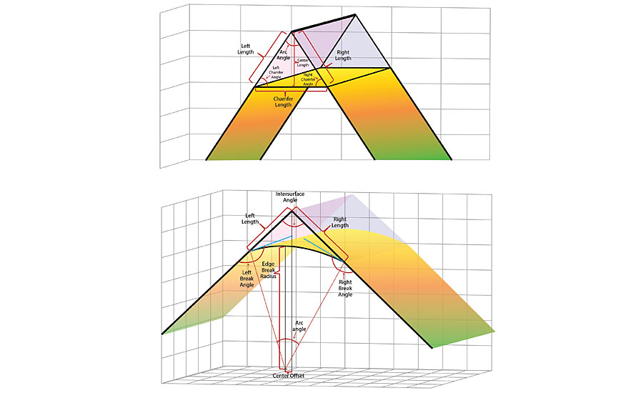
The parameters on a chamfer (top) and a rounded edge (bottom) that are identified by edge break analysis software, including lengths of material that has been removed.
Handheld 3D Metrology on the Shop Floor
An optical technique that can provide the precision and portability required for shop-floor analysis of chamfers and radii is fringe projection. Fringe projection systems can have a vertical resolution of a few microns if designed with an effective wavelength of the fringes at a few hundred microns. Based on how the fringes are distorted on a 3D surface, the topography of the surface can be determined. However, fringe projection systems typically require multiple cameras or multiple camera frames to acquire this 3D measurement. Using multiple camera frames allows for the phase-shifting needed to acquire the 3D surface data, but using multiple camera frames makes fringe-projection systems easily affected by vibration and therefore not capable of being handheld on the shop floor.
To achieve vibration immunity and portability with a fringe projection system, a method can be used called polarized structured light (PSL). These systems rely on fringes generated with polarization interferometry. Using a camera with a micro-polarizer array, four phase-shifted data sets can be attained simultaneously. The micro-polarizer array consists of small polarizers in front of individual camera pixels oriented at 0°, 45°, 90°, and 135°. With two orthogonally polarized wavefronts creating the interference fringes, the micro-polarizer array can introduce the phase shifting usually only seen with multiple camera frames. This technique allows 3D measurements to be taken with one camera and one camera frame, achieving the vibration immunity and portability needed for shop-floor metrology. Now, an inspector can take a PSL instrument to any part and secure 3D surface maps. Such a system could also be placed on a robotic arm for full automation of measurements.
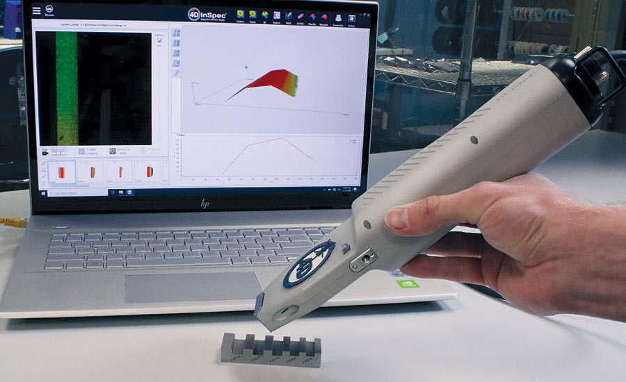
A handheld PSL system measuring a chamfer on an edge break standard.
Edge Break Analysis of 3D Measurement
With the ability to acquire 3D surface data, extensive data-processing techniques are needed to analyze edge break measurements. A PSL system, as described here, acquires millions of data points per measurement, and not just along a single trace. This allows any anomalous data to be eliminated. Using software analysis, the data points can then be fit to the planes of the edge’s sides. Depending on the edge break’s shape, the surface between the sides is fit as a chamfer plane or the best fit cylinder to a rounded edge. With 3D data, more points allow for more confidence in the lengths that can be mathematically calculated. The data points identified as planes or curved surfaces can be realigned so that all calculations are guaranteed to be exactly perpendicular to the edge. Through this normalization, any alignment errors, such as those that were seen with 2D measurements, are eliminated.
In addition to eliminating any anomalous points and realigning the data, analysis software can extrapolate theoretical distances and geometries of material that was removed from the part. The analysis software can calculate the distance between where a side plane ends and where the two side planes would intersect. Angles between these planes as well as any other parameters desired by manufacturers can be determined in seconds.
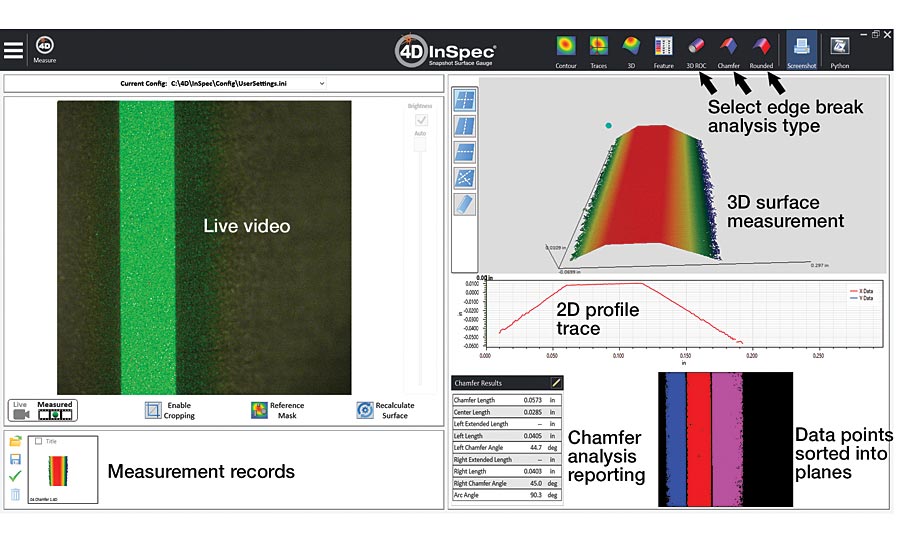
Software analysis of a chamfer. The 3D surface map, calculated chamfer parameters, and data points the software identified as part of the three individual planes can be seen.
Performing measurements this quickly expedites turnaround time for parts being measured. What typically takes minutes, hours, or, if being sent to a lab, days to complete is now almost instantaneous. With micrometer-scale resolution and mathematical analysis of the data, any doubt in measurements disappears. As inspectors err on the side of caution when deciding to scrap a part, having greater confidence in your measurements reduces this doubtful gray zone. Using a PSL system, an inspector can confidently measure up to the specification limit. Fewer quality parts are thrown out, and yield is increased.
Edge break measurements have historically been inconvenient and tedious. As performance needs increase, a simple way to measure chamfers and radii is a necessity. A PSL system can take an edge break measurement with the same simplicity as taking a picture of the edge. The software analysis removes any guess work with precision down as far as .002”. All parameters that make up edge break geometry are then displayed instantly within the software window. Q
Looking for a reprint of this article?
From high-res PDFs to custom plaques, order your copy today!


