Optical Shaft Metrology: A New Generation of Measuring Systems Provides Cutting-Edge Precision, Accuracy

This system is illuminating a sample workpiece using a special calibrated light source.
You may be unfamiliar with the term “optical shaft metrology.” But you’ve no doubt experienced the advantages of this technology. Traveling by car or airplane, for example. In fact, it might surprise you to learn that anytime you’ve used a machine with an electric motor, a turbo charger, fuel injection, precision bearings, transaxles or spindles, chances are good you’ve benefited from optical shaft metrology.
Lives depend on the accuracy
“Put simply, optical shaft metrology is a means of measuring components which are highly cylindrical in shape and which are usually designed to rotate—often at great speed,” says Scott Lukomski, director of metrology sales at Jenoptik, one of the leading developers of optical shaft metrology. “This is a vital step in the manufacture of cylindrical parts, especially when a high degree of accuracy is required.”
In many cases, lives may depend on that accuracy. One example is the concentric rotating shafts at the heart of a jet engine or the spool valves which allow the pilot to control an airplane’s hydraulic steering systems.
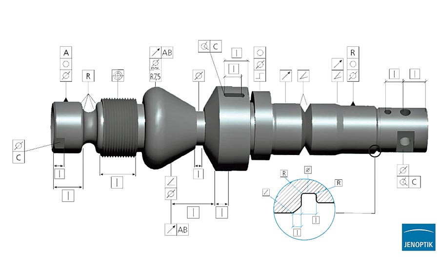
Sample workpiece with examples of solvable measuring tasks.
Precision measurement of parts is a tricky business. Imagine a shaft inside a piece of medical machinery. This imaginary shaft has a fat section, a thin section, a conical section, an eccentric section and a flat section with a hole drilled through it, plus a pulley, a cam, and very fine screw thread at one end. How is it possible to make sure that every section has been accurately machined?
In the past, a quality control inspector would have taken a random selection of finished shafts back to his or her office and, with slide calipers and a micrometer, would’ve begun the painstaking process of examining every aspect of them. Measurements would have been jotted down in a ledger and later compared with a table of acceptable variations.
The inspector would probably have needed a set of pin gages too, and a bore gage, which is used to measure internal diameter. There would also have been an exemplar sitting on the inspector’s desk—a perfect example of the component against which the samples could be matched.
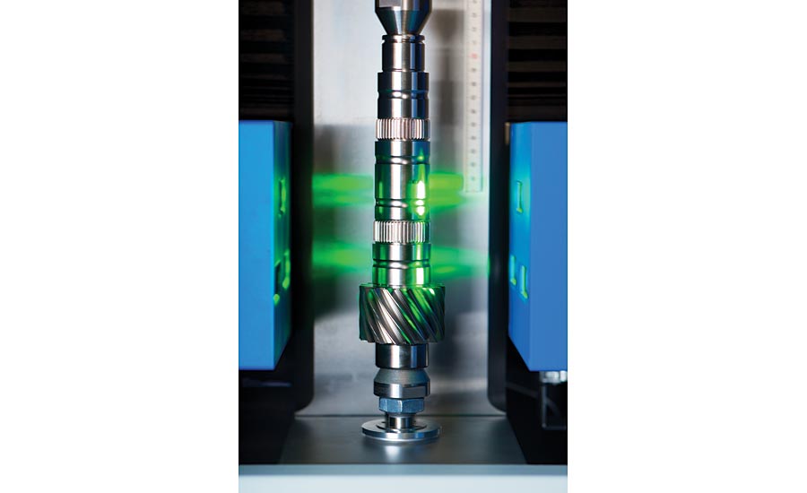
Special calibrated light source and camera working in tandem to measure a finished output/input shaft.
Goodbye to slow and laborious quality inspection
There were myriad problems with this old-fashioned method of quality control. For starters, it was a very painstaking process to complete, and slow, laborious processes don’t fit well with high speed manufacturing systems. Added to that, production lines often had to sit idle while the measurements were checked and machine downtime would cost the manufacturers money, just as it does today.
If a measurement was found to be outside the specified tolerance limits then there would have been yet more downtime required while adjustments were made. Plus, a compromise had to be found between the rate at which quality control samples were taken and the accepted range of variations in product quality. Too many samples meant too much machine downtime but too few tests meant an overall drop in accuracy. Not to mention the tedious, time-consuming and very costly system of quality control was prone to human error too.
Technology has evolved
“Over time, quality control methods have evolved to reduce machine downtime while significantly improving the standard of the finished product,” Lukomski says. “Today, optical shaft metrology is at the very forefront of this evolution, making it the cutting edge of product evaluation and quality assurance.”
For a start, optical shaft metrology units are designed to be installed right on the factory floor, at the heart of the production environment, cutting out that journey to the quality inspector’s office.
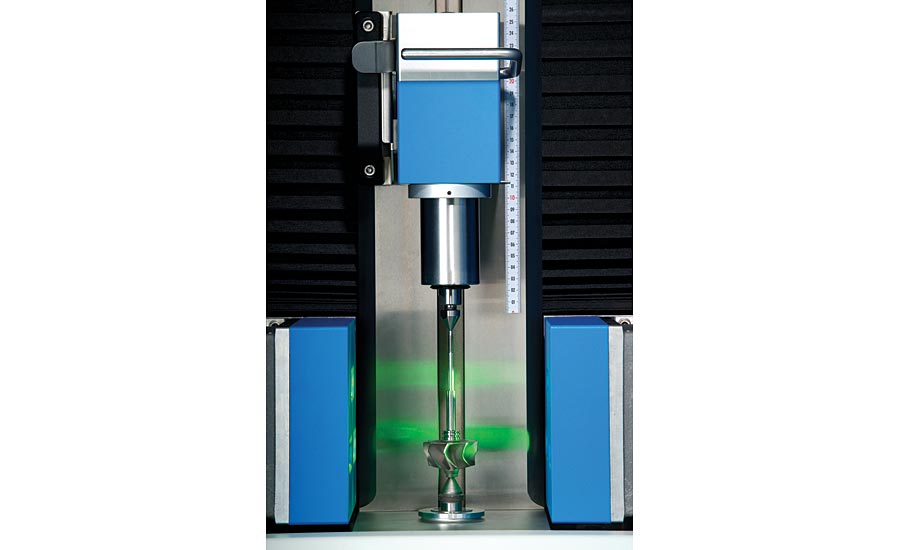
Inside an optical shaft metrology system, showing the camera, light source, adjustable upper center, and lower center.
Secondly, there’s no need for calipers, gages, or perfect part-like masters. Instead, the component is easily and quickly mounted inside a cabinet and all measurements are made automatically, using a special “tuned” light source and camera specifically designed for that purpose. This single sophisticated instrument works to an extraordinarily high degree of accuracy while crucially cutting out the possibility of human error.
You can forget the ledger and comparison tables, too. The latest units record and compare results in an instant and generate reports automatically. They measure diameters, lengths, threads, profiles, and form within seconds—often in less time than it takes to manufacture a single example of the component being tested.
“Machine downtime is cut dramatically,” Lukomski says. “And quicker and more precise quality testing means fewer rejected parts and therefore less waste of expensive raw materials.”
These machines are the result of decades of experience in the field of optical measuring technology. They are easily integrated with stock control and identification systems, such as bar code readers, and they’re capable of comparing a number of production processes simultaneously. Importantly, they’re considerably cheaper and more compact than the alternative coordinate measuring machines, which examine workpiece geometry using a probe and which generally require a specialist operator.
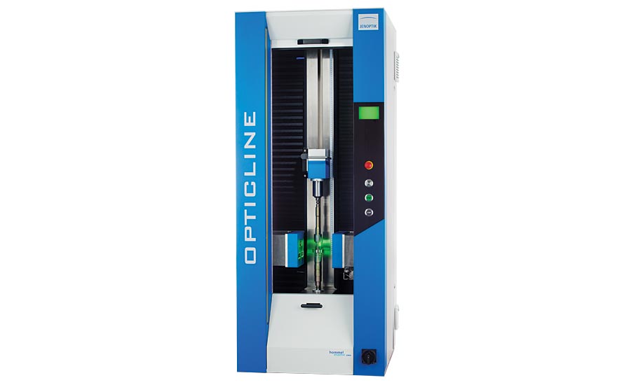
Optical shaft metrology units are designed to be installed right on the factory floor
Consider the forces in play
Camshafts, crankshafts, pinions, and even hypodermic needles found in hospitals are manufactured to a high standard of accuracy using optical shaft metrology, often ensuring both the comfort and safety of end users.
Next time you’re boarding a plane, stop for a moment and consider the jet engine that’s about to propel you to your destination. A Rolls Royce Trent XWB engine features three concentric shafts—that’s a shaft spinning within a shaft spinning within another shaft. The outer, high-pressure shaft turns at around 12,000 RPM; the middle, intermediate shaft at around 9,000 RPM; and the inner, low pressure shaft at around 3,000 RPM. Between them they generate 97,000 pounds of thrust, which in metric terms is the equivalent of being crushed by a 44-ton weight.
With those kinds of forces in play, it’s easy to see why accuracy can be absolutely paramount when manufacturing rotating cylindrical components. Q
Looking for a reprint of this article?
From high-res PDFs to custom plaques, order your copy today!


