Laser scanners capture thousands of points every second, improving reverse engineering and inspection speed and accuracy. As a result, many companies are either replacing their coordinate measuring machines (CMMs) with laser scanners or purchasing laser scanners instead of CMMs. Still other companies are looking at their existing CMM investments and asking if the machines can be preserved or enhanced by equipping them with a laser probe. The answer is yes, a CMM can be equipped with a laser probe at a cost that typically runs only 25% of the cost of a new laser scanner.
CMM popularity
Key advantages of a CMM include the ability to measure individual points to a high level of accuracy and to move from sample location to location under computer control. Trends of the past decade, however, have highlighted several weaknesses.
Part geometry has grown increasingly complicated and, in particular, 3-D contours are becoming more common. As geometric complexity grows, the number of points required for accurate measurements increases at an exponential rate. Frequently, tens of thousands or even millions of points are required to accurately model geometrically complicated parts. The result is that the time needed to capture points one by one has grown to days or sometimes weeks for complicated parts. A contact probe also is limited in the geometries that it can accurately reverse engineer. Some parts have indentations too small for the probe to enter.
Also affecting the usefulness of CMMs is the increasing use of new materials that present problems for contact probes. Some flexible parts make it difficult to contact the surface with a touch probe without creating an indentation that detracts from the accuracy of the measurements. Other parts have surfaces that easily can be scratched or damaged by a CMM probe.
Rise of laser scanning
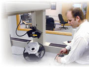
Laser scanning can overcome these problems, making it suited for today's quality control and reverse engineering challenges. Laser scanning systems work by projecting a line of laser light onto surfaces while cameras continuously triangulate the changing distance and profile of the laser line as it sweeps along, enabling the object to be accurately replicated. The laser probe computer translates the video image of the line into 3-D coordinates, providing real-time data renderings that give the operator immediate feedback on areas that might have been missed.
Laser scanners are able to quickly measure large parts while generating a greater number of data points than probes, without the need for templates or fixtures. Because there is no contact tip on a laser scanner that must physically touch the object, the problems of depressing soft objects, measuring small details and capturing complex free-form surfaces are eliminated.
Rather than collect points one by one, the laser scanner picks up tens of thousands of points per second. This means that reverse engineering of the most complicated parts often can be accomplished in an hour or two. Laser scanning can reverse engineer parts that are so complex that they would be practically impossible to measure one point at a time.
The software provided with the scanner simplifies the process of moving from point cloud to a computer-aided design (CAD) model, making it possible in minimal time to generate a CAD model of the scanned part that duplicates the original part.
Special, but readily available software can be used to compare original design geometry to the actual physical part, generating an overall graduated color error plot that shows at a glance where and by how much, surfaces deviate from the original design. This goes beyond the dimensional checks that can be performed with touch probes on CMMs.
Need for laser probe
While many companies have purchased laser scanners, others have made considerable investments in CMMs that are still in excellent condition.
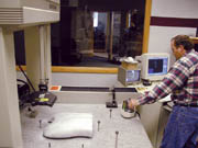
Recognizing that the machine base and motion control system of a laser scanner is nearly identical to that found on a laser scanner, manufacturers have asked if they could upgrade a CMM with a laser probe. Recently, laser probes have become available for existing CMM machines. The laser probe is mounted to the CMM in place of the traditional contact probe. The laser probe comes with a computer that collects the laser scan data and converts it to a 3-D point cloud.
Integrating the laser probe with the CMM is relatively simple; a laser probe, unlike typical touch probes, does not need to be in an exact location to measure because of its large field of view. It needs to know exactly where it was when the data was collected so that the scan data can be accurately positioned in space. With a depth of field ranging from one to several inches, the laser probe must pass through the area of interest on the part.
The most popular method of integration is for the CMM's motion system to guide the probe while the probe computer monitors the encoders to track position. Another option is for the laser probe's computer to actively control the CMM position, even to the point of using feedback from the probe to keep the part surface in its field of view.
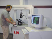
The laser scanner can be operated in either joystick mode or programmed for automated inspection of volume parts. In the joystick mode, the laser probe is attached to the CMM and is controlled by its own computer, which is independent of the CMM's control system. The operator observes the data captured on the probe computer screen, plans and executes the next move, and continues until the desired coverage is achieved.
Alternatively, in an installation that includes a communication link between the probe and CMM controller, the operator can set up moves on the probe computer that are sent to the CMM controller and even modified on the fly to track surfaces in response to feedback from the laser probe. This mode also allows for entire part inspection sequences to be stored, recalled and repeated.
Interfacing mechanics
The first step in interfacing the laser probe to the CMM is capturing the machine position. To achieve this, an encoder interface unit is integrated into the CMM electronics. Some motion transports are so accurate the error contribution relative to the probe is small and can be ignored. Many CMMs, however, are designed to tolerate errors that are mapped and stored for recall to correct raw encoder readings. If the CMM uses this type of volumetric compensation, the native comp table needs to be translated to the probe computer format. The volumetric approach compensates for linearity and squareness errors, but for straightness errors, angle compensation is required.
For straightness correction, it is not practical to simply store large tables of position corrections. Rather, parameters must be stored that characterize the CMM, so that for each position, not only is a corrected X-Y-Z coordinate developed, but an orientation also is supplied. This allows the corrected X-Y-Z to be extended to the active work area of the laser probe. If the CMM controller can accept a trigger from the laser probe, the native correction methods can be used. If the CMM controller cannot accept the trigger, a laser probe correction must be installed.
The laser probe can be mounted to the CMM in any orientation. Once mounted, the orientation relative to the motion transport must be determined. From then on, the laser controller can develop coordinates on the part surface combining probe reference frame coordinates with motion transport coordinates. To measure the relative orientation between the probe and transport, the laser probe control software uses an alignment utility that calls for the probe to be moved around a sphere to derive the transformation.
Equipping a CMM with a laser probe can improve productivity by capturing up to 15,000 points per second, thereby reducing reverse engineering and inspection time. The ability to capture complete geometries rather than a limited number of points improves accuracy. The noncontact laser probe easily measures free-form shapes, delicate parts and difficult geometries. A retrofit is one cost-effective way to take advantage of laser scanning technology.
C. Martin Schuster is president of Laser Design Inc. (Minneapolis), and Robert Thoreson is vice president of the company. For more information, call (952) 884-9648 or visit www.laserdesign.com