Quality Innovations: Noncontact CMMs Laser into 3-D
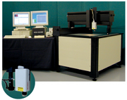
Source courtesy Acu-Gage Systems
Since the 3-axis touch-probe coordinate measuring machine (CMM) and the 2-axis video CMM were invented, each style of machine has occupied its own gaging niche. But now, technology is beginning to blur these niches.
Touch-probe CMMs were the ideal solution for inspecting formed, molded and machined parts. The touch-trigger probe or stylus transmitted X, Y, Z point data, which was then used to calculate solid or spherical geometries. Typically, these points were entered one at a time, so the gaging process for a complex part could take hours or even days. Since formed or machined parts can carry significant weight, most touch-probe CMMs were made out of durable materials, such as granite or high-grade composite materials that could withstand the weight of the part without deflecting the table surface of the measuring machine. In manufacturing operations where 3-D measuring was critical, a touch-probe CMM provided a valuable gaging tool.
However, other manufacturing disciplines did not have inspection requirements for complex formed parts and did not need to measure in the Z-axis. These manufacturers made flat parts, such as stamped metal, printed circuit boards, labels and gaskets. Using materials that didn’t weigh as much as cast or machined parts, these parts were more flexible than steel, which precluded the use of a touch-probe interface for gaging.
To meet these 2-D needs, the video CMM incorporated a video camera in place of a touch probe. Because they didn’t need to support comparable weights as their touch-probe brethren, video CMM platforms were made out of lighter materials such as aluminum or steel. Most video platforms were a cantilever design, where a small X/Y stage transported the part to a stationary camera position. Some designs modified this to having a Y stage that moved front to back with a camera head that moved along an X-axis beam.
Evolution
As video technology evolved, video CMM manufacturers integrated advanced frame grabber technology to automate the point entry process. This automatic edge detection feature processed multiple points along edges or shapes simultaneously, allowing video CMMs to offer increased repeatability, more data points from which to calculate features and faster gaging throughput.
Video CMMs, some using laser triangulation grids and automatic focus, could offer some limited 3-axis capability. But, while video was effective at checking plane to plane heights, as a gage for complex 3-D solid parts, video CMMs weren’t as accurate or efficient as touch-probe CMMs.
So, each style of CMM, touch probe and video, carried its own set of strengths as well as weaknesses. What if the two machines could combine into one single platform? Could there be one all-purpose machine that could achieve 3-D measurement with the improved throughput of video CMMs?
The first attempts to combine the two types of CMMs involved adding video to an existing touch-probe platform, or appending the touch probe to an existing video platform. But the resulting combinations did not address the central issues of speeding up the data entry on the touch-probe interface and capturing more data points per feature. The touch probe still acquired a single point at a time, or scanned at a much slower speed than the video interface on the dual-sensor machines. How could the 3-D point entry match the speed of the video interface and achieve the same measuring accuracy as a touch probe?
Acu-Gage Systems (Manchester, NH) has interfaced a touch probe with its existing video CMM, as had many other CMM manufacturers. Manufacturers had also experimented with various laser-triangulation interfaces, either for point-to-point height measuring or for limited scanning applications. After assessing the capability of a laser system from Optimet (Danvers, MA) called ConoProbe, Acu-Gage saw the opportunity to enhance the functionality of its own video CMM models. The result is a new product called ConoVision.
The ConoProbe interface was integrated into a Quadra-Chek 5000 platform, a metrology software product from Metronics (Bedford, NH). The Quadra-Chek, which uses Windows-NT based icon-driven software, offers a robust platform that can either be set to “point cloud” mode, for reverse engineering of parts, or it can use point filtration to eliminate outlier points, retaining the “best points” for calculating 3-D measurements.
The Acu-Gage ConoVision matched the 2-D speed of their gantry style video CMM platform with the scanning capability of Optimet’s conoscopic holography laser. To ensure the robustness of the video and laser combination, the ConoVision was engineered with 0.1-micron (0.0001 millimeters) linear scales from Heidenhain (Schaumburg, IL) for high resolution. This machine has no probes to physically switch and there is no need for recalibrating probes after changing from the video to the laser interface. The ConoVision is a dual-sensor, noncontact machine that is fully 3-D in its gaging capability.
Conoscopic holography
The critical component in this configuration is the Optimet ConoProbe laser interface that is based on an optical technology called conoscopic holography. The ConoProbe can view through the video lens of the high power laser, measuring distances using the video’s own lens. The collinear geometry removes many artifacts related to triangulation probes.
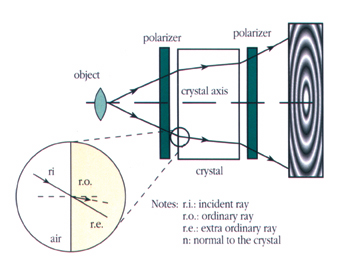
Conoscopic holography is a holographic technique based on light propagation in uniaxial crystals. In the basic interference setup a point of light is projected on a diffuse object. This point creates a light point, which diffuses light in every direction. In a conoscopic system, a complete solid angle of the diffused light is analyzed by the system. The measurement process corresponds to the retrieval of the distance of the light point from a fixed reference plane.
To better comprehend the system functionality, the behavior of a single ray needs first to be understood. A single ray, at a given angle, emitted by a light source point, impinges on the first face of a crystal. It is split into two rays propagating inside the crystal at different velocities along almost the same geometrical path. The velocity of one is isotropic, which is called ordinary, while the other has an anisotropic velocity, which is called extraordinary. Thus, two superposed rays emerge from the crystal with a phase difference at orthogonal polarizations. In order for both rays to interfere, an analyzer aligns the directions of the electrical fields.
For a complete solid angle, each emerging ray has a different phase-
difference between the ordinary and extraordinary rays. At a given plane, the collections of all the rays create an intensity figure, which is the conoscopic figure. The parameters of this figure will depend on the angular distribution of the rays inside the crystal. These depend on the position of the point in space. Recording and analyzing the figure permits the retrieval of the geometrical parameters of the point. Several types of figures can be observed depending on the polarizer and analyzer, and on the crystal optical axis direction.
Different from laser triangulation
The ConoProbe differs from conventional triangulation systems.
1. Dynamic range: The ConoProbe maintains high precision and reproducibility over a wide working range. In most cases, the precision and reproducibility is better than 1/8,000th of the working range. This is an improvement by a factor of 5 to 10 from standard systems and equates to higher resolution.
2. Surface quasi independence: The ConoProbe measures a wide variety of surfaces, which could be measured only with great difficulty by noncontact measurement before.
3. Grazing incidence measurement: The ConoProbe is able to measure at angles very close to grazing incidence. The ConoProbe measures up to
85 degrees from normal incidence on diffusive surfaces from all directions. This again is in contrast to competing triangulation methods.
4. Multi-use single head: Changing an objective lens allows for accuracy ranges from sub-micron to tens of centimeters using a single ConoProbe head.
5. Measurement of bore holes and other hard to measure geometries: The ConoProbe’s unique design permits measurement of narrow and deep holes. Since the ConoProbe is collinear, blind corners can be measured with bending optics.
Integrating conoscopic holography with video technology opens up new opportunities for noncontact gaging that had been the exclusive domain of touch probe CMMs. Noncontact CMMs now combine high accuracy three-dimensional measuring with high throughput and are, for many applications, a faster measuring alternative to touch-probe CMMs.
Tech Tips
1. The video system served as a base, and a touch probe and laser system were added.
2. The critical component in this configuration is the laser interface that can view through the video lens of the laser and measure distances using the video’s own lens.
3. Conoscopy is a simple implementation of a particular type of polarized light interference process based on crystal optics. In the basic interference setup, a point of light is projected on a diffuse object.
Looking for a reprint of this article?
From high-res PDFs to custom plaques, order your copy today!


