Quality Test & Inspection: Failsafe Leak Testing

Failsafe leak testing, where one never misclassifies a bad part as a good part, is doable. Better yet, good parts are never misclassified as bad parts and yield is maximized. However, this standard of perfection is achievable only if one understands and manages all the factors that can undermine leak-testing integrity. By understanding the limitations of failsafe leak testing in the most widely applicable method, mass flow leak testing, practical steps can be taken to manage these factors so that quality standards are uncompromised.
Upstream vs. Downstream Testing
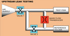
Whether a mass flow leak test is conducted upstream or downstream impacts both the difficulty of testing and the likelihood of making it failsafe.In upstream testing, a part is pressurized and the leak rate is determined by measuring what leaks into the part to replace what is leaking out. If the testing requirements are not as rigorous and the pressure requirements are not that high-for example, leak testing a casting at 10 psi-an upstream test will usually suffice.
Downstream leak testing is used for difficult applications that require testing at pressures in excess of 150 psi, short test times, measurement of small leaks, very accurate and repeatable results or precise temperature compensation.
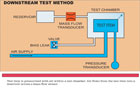
A downstream leak testing system consists of a sealed chamber that encloses all or part of the test item and a second sealed chamber, or reservoir, that has a volume similar to the volume between the test chamber and the test item. Prior to the leak test, the test chamber and reservoir are open to the atmosphere or they can be evacuated to a test vacuum or pressurized to a specific pressure, depending on application requirements. When the leak test is initiated, both volumes are isolated from the chamber pressure source and sealed. The test part is then pressurized to test pressure. Any leakage from the test part flows into the test chamber, causing its pressure to increase. Because the reservoir is still at the initial pressure, part leakage will flow through the mass flow transducer into the test chamber. Output from the mass flow transducer is a direct measure of the leakage of the test part. Because the mass flow transducer is not exposed to the test part pressure, the measurement it provides is independent of pressure.
The downstream method has the advantage of providing faster test times because the volume affecting the leak system response and the related stabilization time required is minimized. The best-in-class mass flow sensors are custom tuned for maximum stability in relevant ranges and, as a result, can accurately measure very small test part leaks.
The downside of downstream testing is the added cost of tooling needed to perform the test. When failsafe leak testing is the goal, the promise of greater accuracy usually makes downstream testing the method of choice. Sometimes the high pressure under which products or components function-and at which they must be leak tested-also mandate that the downstream testing method be used, despite the added costs for downstream test fixturing.
Bias Leaks
In downstream mass flow testing where there is zero pressure from atmosphere, it is not possible to know if the valve used in testing is working unless extra steps are taken. Otherwise, a zero leak measurement could be caused by a valve not working or a line being plugged.To compensate for this possibility, and to make the testing failsafe, the more accurate systems employ a bias leak, which verifies that the entire system is working and that the test circuit’s integrity is not compromised. A bias leak is simply the introduction of a known leak as a self-check of the testing system. If valves are not operating properly and test seals are insufficient, the bias leak will not measure as a leak, indicating that remedial actions on the test system need to be taken. Ideally, introducing a bias leak should not affect test circuit design and volume.
Calibration and Validation
Failsafe leak testing also requires that systems be calibrated and validated frequently. For leak testing systems that still rely on relatively slow, antiquated off-line mechanical calibration methods, the failsafe leak-testing standard is rarely achieved because production pressures do not allow for frequent recalibrations. At best, mechanical calibration methods can only achieve a repeatable and reproducible accuracy of 0.1 standard cubic centimeters per minute (sccm). In addition, they have inherent limitations such as pneumatic valves and other moving parts that can stick or wear, as well as small gaps or orifices that are likely to change due to clogging. Mechanical calibration methods are also prone to operator error.Updated electronic technology for self-calibration and automatic validation of leak testing can now achieve an accuracy of ±2% of reading or 0.02 sccm, which allows manufacturers to maintain the highest quality standards without slowing production line output for time-consuming mechanical calibration. Unlike mechanical calibration methods, the calibration process is automatic and no operator judgment is required. Because production delays involved with off-line mechanical calibration are eliminated, operators not only achieve higher accuracy but higher production yields, as well.
Temperature Compensation
Because mass flow sensors are temperature transducers, failsafe leak testing also requires a method to compensate for temperature effects on test readings, for example, the temperature of the part relative to the ambient temperature.When using mass flow leak testing, test measurements are created by a decrease in the number of air molecules (the leak) in the test volume and an apparent or virtual leak caused by adiabatic heating or cooling, trapping or part temperature effects.
Typically, the dominant thermal effect in leak testing results when a part is at atmospheric pressure and the ambient temperature is pressurized. The warmer air temperature then cools to the temperature of the part. If a part is at atmosphere and then evacuated, the reverse occurs. Thus, adiabatic heating or cooling must be managed by the test system to achieve reliable results. This is best done with volume fillers that reduce the quantity of air being compressed and the response time of the system by decreasing the distance air molecules travel before reaching the fixture or test part walls.
The rate at which a part reaches ambient temperature is proportional to the difference between the part temperature and the ambient temperature. When a cool part is pressurized, the test air will cool down toward the temperature of the part. As the part temperature rises toward ambient, the test air temperature will rise with the part temperature, increasing the air pressure and creating a virtual leak that will mask the actual leak. Alternately, the reverse occurs if the part is warmer than ambient.
All of these processes are known physical processes that will alter test readings if there is no instrumentation to measure and compensate for virtual leaks masking real leak rates. Unfortunately, many who are less schooled in the underlying mechanisms of leak test requirements still do not manage these temperature effects and, therefore, mistakenly conclude that mass flow leak testing is only viable for gross leak testing applications; in reality, the better mass flow leak testing systems that can compensate for temperature are accurate for leaks as small as 0.05 sccm.
Temperature compensation involves automatically differentiating between the actual leak and the virtual leak comprising the test measurement. Leak testing without automated temperature compensation is always questionable and does not allow for adequate gage repeatability and reproducibility in most applications.
Test-Centric Assembly
Upfront consideration of the testing requirements helps create test-centric assemblies that are able to achieve the failsafe leak-testing standard. Reliably accurate leak testing also requires failsafe mechanisms for circuit switching as well as verification that the valves involved in the test circuit are fully operational at every test. Valves that fail will mask leaks; any testing that does not include verification of the test circuit cannot be relied on. Also, fixture design is critical to failsafe leak testing and requires a different skill set than production line machine building where fixtures are meant to simply hold parts in place during assembly.There is significant variation in yields from leak testing-intensive manufacturing operations, from one plant to another. Often, those with lower yields or substandard quality do not understand the real world requirements of test-centric assembly such as temperature compensation methods, using bias leak testing, or the need for electronic inline calibration and validation methods. Enlisting the services of engineers who have a singular focus on leak testing is recommended to create the system capabilities that enable a failsafe leak-testing standard. Q
Jacques Hoffmann is founder and president of InterTech Development Co. (Skokie, IL). For more information, call (847) 679-3377, e-mail [email protected] or visit www.intertechdevelopment.com.
Tech Tips
Looking for a reprint of this article?
From high-res PDFs to custom plaques, order your copy today!


