GD&T Workshop: The Fundamentals of GD&T
The many little pieces that make up the world of GD&T.
How far have we gotten? In our first workshop we took a 30,000-foot view down onto GD&T to promote the idea that GD&T is a symbolic language with which to encode the functions of each feature of a part and specify permissible limits of imperfection to guarantee assembly and operation. In our second workshop, we took a detailed look at the perfect imaginary world of GD&T, namely the world of tolerance zones, tolerance values, Datums, Datum Reference Frames, Basic dimensions, and an example of the symbolic language with which we impose the perfect imaginary world on the imperfect real world of physical parts. In our third workshop, we got to know something about the imperfect world of real part features, and provided some insights into the Geometry Control Tools used to impose constraints on their size, form, orientation and location. In the current workshop, we will use a discovery tour to get a handle on some fundamental concepts and eliminate some common misconceptions that always get in the way of the effective use of GD&T, and cause lots of us to think it’s Grim, Depressing & Troublesome instead of Grand, Delightful & Tantalizing. Here we go!
A Datum Feature Label.
A CAD representation of Datum Feature A.
A wavy line representing the true nature of Datum Feature A.
Datum A – a perfect tangent plane on Datum Feature A, which, if A is slightly convex, can and may rock back and forth, namely be slightly unstable. (See the ASME Y14.5 2009 defined Rule of Rocking & Rolling Datum Feature Simulation - §4.11.2 p.59).
A Flatness Feature Control Frame. The “decoding:” “Flatness requires all points on Datum Feature A to lie within a slab-like tolerance zone of thickness 0.1 millimeter with no external constraints.”
The unconstrained, slab-like, Flatness tolerance zone.
The Basic dimensions that serve to locate the Position tolerance zone defined for the central bore. Definition: Basic dimensions are fixed, always appear in rectangular frames, and serve only to orient and locate tolerance zones and Datum Targets.
“The True Position” of the central bore, namely the “Basic location” of its Position tolerance zone as defined by its associated Basic dimensions.
Datum Feature label “B.”
A Perpendicularity Feature Control Frame. The “decoding:” “Perpendicularity requires all points on Datum Feature B to lie within a slab-like tolerance zone of thickness 0.1 millimeter which is perpendicular to the base plane of a Datum Reference Frame (DRF) established using Datum Feature A simulated “rocking.” (See the ASME Y14.5 2009 defined Rule of Rocking & Rolling Datum Feature Simulation - §4.11.2 p.59).
The singly orientation constrained, slab-like tolerance zone defined by the Perpendicularity tool.
The True Position tool. Yes, many people refer to this as the “true” Position tool, but it is in fact only the “Position” tool. See item 8 for a definition of the “True Position.” The “decoding:” Position requires the bounded axis of the bore to lie within a cylindrical tolerance zone of diameter 0.05 millimeters Regardless of Feature Size, which is oriented and located by Basic dimensions relative to a Datum Reference Frame established using Datum Feature A simulated “rocking,” Datum Feature B simulated “rolling,” and Datum Feature C simulated stably.”
The cylindrical tolerance zone shape modifier, which specifies the shape of the tolerance zone and makes clear that the tolerance value represents the diameter, not the radius of the zone.
The “tolerance value,” namely the size of the imposed tolerance zone.
A “Tolerance Zone Size” modifier, in particular the Regardless of Feature Size modifier (S), which makes clear that the tolerance value is (S)tuck. Definition: When associated with a tolerance value, the Material Condition modifiers (S), (M) and (L) impact the size of the tolerance zone. (S) causes the tolerance value to be (S)tuck, (M) permits (M)ore tolerance as the controlled feature departs from its Maximum toward its Least Material condition, and (L) permits (L)ots of tolerance as the controlled feature departs from its Least toward its Maximum Material condition. Note: The ASME Y14.5 2009 Standard forbids the use of an explicit (S) modifier in an attempt to get closer to the ISO 1101 Standard, which has never recognized an explicit symbol. The author considers this to be a step backward, and recommends its continued use in association with a drawing note taking exception to the rule, in order to make clear that the (S) is intentional, not an oversight, and in order to accelerate and clarify the Feature Control Frame “decoding” process.
The letters in the last compartment of a Feature Control Frame represent Datum Features, not Datums. They also represent an ordered set of instructions for establishing a Datum Reference Frame (DRF), namely a coordinate system relative to which Basic angles and Basic linear dimensions serve to orient and locate tolerance zones.
The Diameter tool. This tool, which is beholden to the Envelope Rule by default, defines upper and lower limits on the diameter of bores and shafts. The “decoding:” “The Diameter tool requires all points on the surface of the bore to lie within a tube-like tolerance zone of wall thickness varying between 0 and 0.1 millimeter, whose in-space boundary is a perfect cylinder of diameter 24.95 millimeters, and whose in-material boundary is spaghetti-like with a local diameter of 25.05 millimeters, on which there are no external constraints.”
The axes of the DRF established using Datum Features A, B and C, represented using the DRF axis labels introduced in the ASME Y14.5 2009 Standard.
The tube-like tolerance zone of variable wall thickness defined by the Diameter tool.
The cylindrical tolerance zone defined by the Position tool.
The symbolic language of GD&T is complex, but no more complex than the imperfect real world of the features of the physical objects it must address. It gives the impression of being a jungle, but with patience and perseverance, we see that it is in fact an English garden, that it can but may not be interpreted, and that it can and must be “decoded,” which of course is only possible if it has been properly “encoded.”
Note: We continue to encourage readers to submit questions, and look forward to providing succinct answers to as many as possible.
Datum Feature Simulators are almost perfect, inverse Datum Features 1) from which we extract Datums, 2) in which we first establish Datum Reference Frames, and 3) with which we transfer Datum Reference Frames to actual parts.
Datums are the minimum, mutually embedded set of a single, perfect imaginary reference point, and/or line, and/or plane which together, fully characterize the orientation and location of a Datum Feature Simulator, and which serve to constrain the degrees of freedom of a “starter” coordinate system, thereby turning it into a Datum Reference Frame.
Datum Reference Frames are Cartesian (or polar or spherical) coordinate systems established using a set of Datums extracted from a set of Datum Feature Simulators, defined by a set of Datum Features referenced in a Feature Control Frame.
How far have we gotten? In our first workshop we took a 30,000-foot view down onto GD&T to promote the idea that GD&T is a symbolic language with which to encode the functions of each feature of a part and specify permissible limits of imperfection to guarantee assembly and operation. In our second workshop, we took a detailed look at the perfect imaginary world of GD&T, namely the world of tolerance zones, tolerance values, Datums, Datum Reference Frames, Basic dimensions, and an example of the symbolic language with which we impose the perfect imaginary world on the imperfect real world of physical parts. In our third workshop, we got to know something about the imperfect world of real part features, and provided some insights into the Geometry Control Tools used to impose constraints on their size, form, orientation and location. In the current workshop, we will use a discovery tour to get a handle on some fundamental concepts and eliminate some common misconceptions that always get in the way of the effective use of GD&T, and cause lots of us to think it’s Grim, Depressing & Troublesome instead of Grand, Delightful & Tantalizing. Here we go!
A Discovery Tour
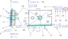
In the drawing included here, lots of bits and pieces of the world of GD&T have been singled out and numbered. Each numbered arrow points to a particular piece of the puzzle. In the best of all possible worlds, readers will put a little group of devotees together and do battle over how to describe what each arrow points to before checking our explanations. After each round, compare your explanations and ours, and if you find ours incorrect or incomplete, send us an email recommending improvements, because we are here to get it right, not to prove we are right, and the sooner proven wrong the better.A Datum Feature Label.
A CAD representation of Datum Feature A.
A wavy line representing the true nature of Datum Feature A.
Datum A – a perfect tangent plane on Datum Feature A, which, if A is slightly convex, can and may rock back and forth, namely be slightly unstable. (See the ASME Y14.5 2009 defined Rule of Rocking & Rolling Datum Feature Simulation - §4.11.2 p.59).
A Flatness Feature Control Frame. The “decoding:” “Flatness requires all points on Datum Feature A to lie within a slab-like tolerance zone of thickness 0.1 millimeter with no external constraints.”
The unconstrained, slab-like, Flatness tolerance zone.
The Basic dimensions that serve to locate the Position tolerance zone defined for the central bore. Definition: Basic dimensions are fixed, always appear in rectangular frames, and serve only to orient and locate tolerance zones and Datum Targets.
“The True Position” of the central bore, namely the “Basic location” of its Position tolerance zone as defined by its associated Basic dimensions.
Datum Feature label “B.”
A Perpendicularity Feature Control Frame. The “decoding:” “Perpendicularity requires all points on Datum Feature B to lie within a slab-like tolerance zone of thickness 0.1 millimeter which is perpendicular to the base plane of a Datum Reference Frame (DRF) established using Datum Feature A simulated “rocking.” (See the ASME Y14.5 2009 defined Rule of Rocking & Rolling Datum Feature Simulation - §4.11.2 p.59).
The singly orientation constrained, slab-like tolerance zone defined by the Perpendicularity tool.
The True Position tool. Yes, many people refer to this as the “true” Position tool, but it is in fact only the “Position” tool. See item 8 for a definition of the “True Position.” The “decoding:” Position requires the bounded axis of the bore to lie within a cylindrical tolerance zone of diameter 0.05 millimeters Regardless of Feature Size, which is oriented and located by Basic dimensions relative to a Datum Reference Frame established using Datum Feature A simulated “rocking,” Datum Feature B simulated “rolling,” and Datum Feature C simulated stably.”
The cylindrical tolerance zone shape modifier, which specifies the shape of the tolerance zone and makes clear that the tolerance value represents the diameter, not the radius of the zone.
The “tolerance value,” namely the size of the imposed tolerance zone.
A “Tolerance Zone Size” modifier, in particular the Regardless of Feature Size modifier (S), which makes clear that the tolerance value is (S)tuck. Definition: When associated with a tolerance value, the Material Condition modifiers (S), (M) and (L) impact the size of the tolerance zone. (S) causes the tolerance value to be (S)tuck, (M) permits (M)ore tolerance as the controlled feature departs from its Maximum toward its Least Material condition, and (L) permits (L)ots of tolerance as the controlled feature departs from its Least toward its Maximum Material condition. Note: The ASME Y14.5 2009 Standard forbids the use of an explicit (S) modifier in an attempt to get closer to the ISO 1101 Standard, which has never recognized an explicit symbol. The author considers this to be a step backward, and recommends its continued use in association with a drawing note taking exception to the rule, in order to make clear that the (S) is intentional, not an oversight, and in order to accelerate and clarify the Feature Control Frame “decoding” process.
The letters in the last compartment of a Feature Control Frame represent Datum Features, not Datums. They also represent an ordered set of instructions for establishing a Datum Reference Frame (DRF), namely a coordinate system relative to which Basic angles and Basic linear dimensions serve to orient and locate tolerance zones.
The Diameter tool. This tool, which is beholden to the Envelope Rule by default, defines upper and lower limits on the diameter of bores and shafts. The “decoding:” “The Diameter tool requires all points on the surface of the bore to lie within a tube-like tolerance zone of wall thickness varying between 0 and 0.1 millimeter, whose in-space boundary is a perfect cylinder of diameter 24.95 millimeters, and whose in-material boundary is spaghetti-like with a local diameter of 25.05 millimeters, on which there are no external constraints.”
The axes of the DRF established using Datum Features A, B and C, represented using the DRF axis labels introduced in the ASME Y14.5 2009 Standard.
The tube-like tolerance zone of variable wall thickness defined by the Diameter tool.
The cylindrical tolerance zone defined by the Position tool.
The symbolic language of GD&T is complex, but no more complex than the imperfect real world of the features of the physical objects it must address. It gives the impression of being a jungle, but with patience and perseverance, we see that it is in fact an English garden, that it can but may not be interpreted, and that it can and must be “decoded,” which of course is only possible if it has been properly “encoded.”
Note: We continue to encourage readers to submit questions, and look forward to providing succinct answers to as many as possible.
A Few Definitions
Datum Features are specially designated imperfect surfaces of real objects that serve to constrain degrees of rotational and translational degrees of freedom during assembly processes.Datum Feature Simulators are almost perfect, inverse Datum Features 1) from which we extract Datums, 2) in which we first establish Datum Reference Frames, and 3) with which we transfer Datum Reference Frames to actual parts.
Datums are the minimum, mutually embedded set of a single, perfect imaginary reference point, and/or line, and/or plane which together, fully characterize the orientation and location of a Datum Feature Simulator, and which serve to constrain the degrees of freedom of a “starter” coordinate system, thereby turning it into a Datum Reference Frame.
Datum Reference Frames are Cartesian (or polar or spherical) coordinate systems established using a set of Datums extracted from a set of Datum Feature Simulators, defined by a set of Datum Features referenced in a Feature Control Frame.
Looking for a reprint of this article?
From high-res PDFs to custom plaques, order your copy today!


