Inspect with Eddy Current
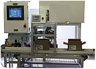
Eddy current inspection systems can improve quality while reducing scrap. Source: NDT Technologies
In this extremely competitive global economy, the reduction of scrap costs is essential to the continued growth and, in fact, perhaps even the survival, of many companies.
If the parts manufacturing process is not properly monitored and controlled so that the production of scrap is not kept at an absolute minimum, the profitability of manufactured parts will quickly disappear. Further, because labor-related part inspection costs in the United States are high, and the visual inspection of parts is no more than 80% effective, the most cost- effective and efficient means to approach the part inspection challenge is with inspection technologies that can be fully automated. If these fully automated inspection processes are located immediately after the machining operation that produces the parts, and the inspection process continually monitored for production related anomalies, the production of scrap can be kept to an absolute minimum.
Within the myriad of inspection systems and technologies available in the industry that are relatively inexpensive and can be fully automated, one inspection technology stands out-eddy current inspection. It is available to the machining industry in two forms: noncontact and contact.
In its noncontact form, eddy current inspection can be used to inspect parts, made from any conductive material, for:
- Cracks, voids
- Thread presence and condition
- Materials thickness
- Materials hardness
- Materials chemistry
- Out-of-round condition and run-out
- Surface and subsurface porosity
- Inclusions and delaminations
- Complex feature presence and condition
Internal cut threads in transmission parts are profiled with a contact-type eddy current probe. Source: NDT Technologies
- Hole ovality, cylindricity and taper measurements to within ±1 micron
- Thread counting, thread condition
- Measurements of multiple part features including pilot hole, thread range, counter bore and chamfer, within one hole with one pass
- Complex surface measurements
- Surface finish
- Bore diameter measurements in noncontinuous holes such as laminate stacks
- Outer diameter thread pitch diameter measurements to within ±0.0005 inch
- Precision weight measurements to within 0.001 ounce
- Precision height measurements to within ±1 micron
In most cases, automated part inspections should occur immediately after a machining operation or, in some cases, a related number of machining operations, to verify that the part has been produced correctly. When this technique is employed, the inspection process is located as far back as possible in the machining process. In the event that a problem does occur, manufacturing problems can be caught immediately, before any number of parts is manufactured with a common anomaly. In doing so, scrap costs are inherently kept to an absolute minimum.
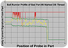
The graph shows a ball runner profile of bad part #8 (marked OS thread). Source: NDT Technologies
Flexibility
The flexibility of both of these eddy current inspection techniques allows them to be employed to inspect multiple part features, or even multiple hole features, simultaneously. For example, any number of holes in an engine block can be inspected for thread presence and condition at the same time. Further, if the holes being inspected include multiple features, such as intersecting holes, counter bores or chamfers in addition to threads, all of these individual features can be inspected with one inspection process, at the same time. This inherently decreases inspection-related costs and the complexity of the overall inspection process, while inherently increasing throughput.An additional advantage of inspection systems of this type is that they use the statistical variations of the manufactured parts to determine the accept/reject limits for the inspection. During a “learn” process, the operator causes the inspection system to learn the characteristics of some number-typically 10-of known good parts.
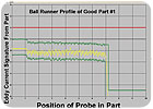
The graph shows a ball runner profile of good part #1. Source: NDT Technologies
As the inspection process commences, the system automatically finds its own set of good and bad master parts. As the system rejects parts that fall outside the ±3 sigma limits that have been established with the “learn” of the initial 10-part sample, they should be independently gaged to determine if they are, in fact, good or bad. If they meet the print requirements, and are good, the initial ±3 sigma limits should be widened so that these parts are accepted. If it is determined that they are bad, the limits should not be readjusted, and the parts kept at the inspection station and used as “bad rabbit parts.” The bad rabbits can then periodically be run through the system to qualify the inspection systems reject capability.
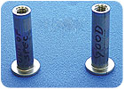
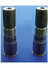
Cut threads in threaded fasteners are profiled with a contact-type eddy current probe. Source: NDT Technologies
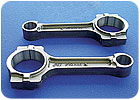
Cut threads and complex hole geometry in connecting rods are profiled with a noncontact-type eddy current probe. Source: NDT Technologies
Looking for a reprint of this article?
From high-res PDFs to custom plaques, order your copy today!


