Advances in Videoscope Technology
Borescope and videoscope technologies have advanced dramatically since their beginnings. As such, a refresher of borescope technology evolution may be in order.
Borescope and videoscope technologies have advanced dramatically since their beginnings.
As such, a refresher of borescope technology evolution may be in order.
The rigid borescope is a rather straightforward lens tube optical system; its limitation being straight-line access required to access the inspection site. Typically configured with rod lenses and an objective lens of variable fields of view, it offers the highest resolution and may be designed to observe in different and unique directions from its access of insertion.
Typical viewing directions, based on application include: side viewing (90 degree direction of view), direct viewing (0 degree direction of view), fore-oblique (30, 45 or 70 degree direction of view) and retrospective (110 degree direction of view), where a borescope is actually looking toward the entrance port of the inspection and almost back on itself.
The magnification of the optical system is dictated by the field of view. The narrower the field of view of the borescope, the higher the objective target magnification and vice versa. System brightness is determined by aperture design in the objective and may maximize brightness at a fixed or limited focal range or average the same over a greater depth of field.
Advances in mechanical capabilities and dispersed fiber optical illumination led to the introduction of the swing prism borescope, a borescope with an optical tip that can actually swing, or scan, via remote operation from the proximate end of the borescope, covering a viewing field from 0 degree direct viewing to 130 degrees retrospective. Coupled with the ability to rotate the insertion tube, these rigid borescopes combine the utility of what were once larger inventories of multiple dedicated direction-of-view borescopes with a 400-degree circumferential viewing area.
Additional magnification may be added to any borescope, and recent developments include integral zoom capability and proximate zoom adapters. The detriments are as with typical photographic imaging-the more interfaces, the greater the light losses and darker the image.
The first flexible instrument that greatly enhanced remote inspection was the flexoscope, a borescope with fiber optic illumination and a cohesive image bundle that relays the image back to the proximate eyepiece. The flexoscope also incorporates an articulating distal end that allows the inspector to vary the direction of viewing in four axes. Variable field of view is available, and image magnification and aperture constraints apply as with rigid borescopes.
 The significant limitation of the fiber optic imaging is the resolution as it is solely a function of pixel, or image fiber, count. The quality of resolution of the fiber optic varies based on individual fiber diameter, measured in microns, and the ability to cleanly and coherently package the fibers to minimize the observed interstitial pattern where fibers are packed and secured into a bundle.
Brightness is a function of the numerical aperture of the fiber, and internal reflection efficiency remains critical in maximizing image brightness. Correct and effective fiber cladding prevents light from radially escaping the fiber in route to the viewing eyepiece of the scope.
Given a specific fiber diameter, typically the larger the fiber optic imager diameter, the higher the system resolution based on fiber, or pixel, count. Light loss over longer fiber optic imagers also is significant, and traditional lengths for effective imaging are limited to two or three meters.
Both the rigid borescope and the fiber optic borescope may be adapted to video cameras for video display. Again, the adaptive interfaces lead to light loss and affect displayed image brightness.
The most advanced and preferred borescopic instrument is the videoscope. Based on dedicated video imaging and an imager that is present at the distal end of the flexible borescope, the videoscope achieves unparalleled resolution and image brightness. The charged-coupled device, or CCD imager, is designed with thousands of photo sensitive cells, and the image is created at the distal tip of the videoscope. This means image brightness is now a function of what is present at the tip of the videoscope, at the observation site, and there is essentially no light loss based on insertion tube length. Standard and previously discussed optical principles apply to direction of view and field of view, coupled with application specific and effective aperture designs.
Destructive test or inefficient use of assets costs money. Borescopic measurement and defect quantification are now of paramount importance. The latest videoscope measurement technology actually reduces the cost of equipment ownership given a new means to determine optical characteristics necessary to measure.
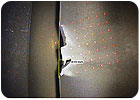
Laser true measurement technology uses standard inspection optics to provide quantifiable and accurate results. Laser true measurement achieves what has eluded manufacturers since borescopic measurement was first introduced-a quick, effective and easy means to quantify data. A standard videoscope with a general inspection optical tip, designed for maximum brightness, can now perform accurate measurements live or on stored images for post-inspection image analysis. The videoscope is equipped with ancillary laser illumination via an optical fiber that readily projects a “grid” onto a target worksite. This diverging pattern is passively observed and captured by the CCD imager in the videoscope by simply pressing a button on the videoscope control body. The observed pattern (relative dot position) varies from image to image as a function of the videoscope working distance and its orientation to the target surface. The processor passively interprets the data and permanently stores this data history with the image.
The second and final step is to position the video cursor for measurement with text, specific annotation or other relevant information easily superimposed via the integral QWERTY keyboard. A critical step of the measurement process is the actual displacement of the video cursor during the measurement and its own resolution of position. A larger monitor with a smaller measured distance, or incremental change per cursor move (pixel travel), will yield the most detailed and accurate measurement-it is desirable to resolve 0.001 inch per cursor move without electronically “zooming” the image, which ultimately degrades resolution.
The technology is not limited to basic white light visual inspection. There is now a UV videoscope designed to support visual fluorescent penetrant inspection (FPI) needs. A UV light source is coupled to the UV videoscope delivering high intensity ultra-violet light to the work surface via special illumination fibers with higher transmission efficiency in the 365-nanometer range. The processor assists the FPI inspector with portable and quantifiable results.
The borescope and videoscope technologies have advanced dramatically since the early 1980s when the smallest common diameter was 16 millimeters, the lightest processor included a cathode-ray tube (CRT) monitor and a system required a separate and detached 300-watt Xenon light source. The complete system weighed in at close to 100 pounds when packaged for field use and transportation. Inspection tools are now more portable. The inspection processes are more thorough, efficient, more easily accomplished and more reliable than ever before, given the advances of the core imaging technology. NDT
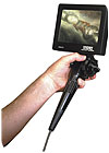
Sharing information is critical and the larger LCD (as seen here) is ideal for larger audiences, long distance viewing and training purposes. Source: Karl Storz Industrial-America Inc.
Borescope and videoscope technologies have advanced dramatically since their beginnings.
As such, a refresher of borescope technology evolution may be in order.
The rigid borescope is a rather straightforward lens tube optical system; its limitation being straight-line access required to access the inspection site. Typically configured with rod lenses and an objective lens of variable fields of view, it offers the highest resolution and may be designed to observe in different and unique directions from its access of insertion.
Typical viewing directions, based on application include: side viewing (90 degree direction of view), direct viewing (0 degree direction of view), fore-oblique (30, 45 or 70 degree direction of view) and retrospective (110 degree direction of view), where a borescope is actually looking toward the entrance port of the inspection and almost back on itself.
The magnification of the optical system is dictated by the field of view. The narrower the field of view of the borescope, the higher the objective target magnification and vice versa. System brightness is determined by aperture design in the objective and may maximize brightness at a fixed or limited focal range or average the same over a greater depth of field.
Advances in mechanical capabilities and dispersed fiber optical illumination led to the introduction of the swing prism borescope, a borescope with an optical tip that can actually swing, or scan, via remote operation from the proximate end of the borescope, covering a viewing field from 0 degree direct viewing to 130 degrees retrospective. Coupled with the ability to rotate the insertion tube, these rigid borescopes combine the utility of what were once larger inventories of multiple dedicated direction-of-view borescopes with a 400-degree circumferential viewing area.
Additional magnification may be added to any borescope, and recent developments include integral zoom capability and proximate zoom adapters. The detriments are as with typical photographic imaging-the more interfaces, the greater the light losses and darker the image.
The first flexible instrument that greatly enhanced remote inspection was the flexoscope, a borescope with fiber optic illumination and a cohesive image bundle that relays the image back to the proximate eyepiece. The flexoscope also incorporates an articulating distal end that allows the inspector to vary the direction of viewing in four axes. Variable field of view is available, and image magnification and aperture constraints apply as with rigid borescopes.
Laser true measurement technology uses standard inspection optics to provide quantifiable and accurate results. Source: Karl Storz Industrial-America Inc.
Brightness is a function of the numerical aperture of the fiber, and internal reflection efficiency remains critical in maximizing image brightness. Correct and effective fiber cladding prevents light from radially escaping the fiber in route to the viewing eyepiece of the scope.
Given a specific fiber diameter, typically the larger the fiber optic imager diameter, the higher the system resolution based on fiber, or pixel, count. Light loss over longer fiber optic imagers also is significant, and traditional lengths for effective imaging are limited to two or three meters.
Both the rigid borescope and the fiber optic borescope may be adapted to video cameras for video display. Again, the adaptive interfaces lead to light loss and affect displayed image brightness.
The most advanced and preferred borescopic instrument is the videoscope. Based on dedicated video imaging and an imager that is present at the distal end of the flexible borescope, the videoscope achieves unparalleled resolution and image brightness. The charged-coupled device, or CCD imager, is designed with thousands of photo sensitive cells, and the image is created at the distal tip of the videoscope. This means image brightness is now a function of what is present at the tip of the videoscope, at the observation site, and there is essentially no light loss based on insertion tube length. Standard and previously discussed optical principles apply to direction of view and field of view, coupled with application specific and effective aperture designs.
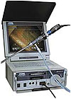
Configurations include a “back pack” with a remote LCD mounted to the videoscope body (as seen here), a rolling case with a 12-inch LCD that telescopes upward for easy viewing, a hard case with the table top unit inside or a base processor with a smaller remote LCD option. Source: Karl Storz Industrial-America Inc.
Remote Visual Inspection
The market demands of videoscope and borescope systems, now commonly referred to as remote visual inspection (RVI) systems, have driven manufacturers to new levels of capability and performance. Expectations include the use of the most advanced technologies integrated with a broad range of videoscope lengths, diameters and CCDs capable of high-resolution digital image processing. A standard platform that allows for use of traditional borescopic inspection products including rigid lens borescopes, fiberscopes as small as 0.5 millimeter in diameter, and videoscopes is essential to meet the variety of inspection needs and applications. Along with demand for the image processor’s technology are requirements for versatility, portability, flexibility and user-friendly packaging.Destructive test or inefficient use of assets costs money. Borescopic measurement and defect quantification are now of paramount importance. The latest videoscope measurement technology actually reduces the cost of equipment ownership given a new means to determine optical characteristics necessary to measure.
Laser true measurement technology uses standard inspection optics to provide quantifiable and accurate results. Laser true measurement achieves what has eluded manufacturers since borescopic measurement was first introduced-a quick, effective and easy means to quantify data. A standard videoscope with a general inspection optical tip, designed for maximum brightness, can now perform accurate measurements live or on stored images for post-inspection image analysis. The videoscope is equipped with ancillary laser illumination via an optical fiber that readily projects a “grid” onto a target worksite. This diverging pattern is passively observed and captured by the CCD imager in the videoscope by simply pressing a button on the videoscope control body. The observed pattern (relative dot position) varies from image to image as a function of the videoscope working distance and its orientation to the target surface. The processor passively interprets the data and permanently stores this data history with the image.
The second and final step is to position the video cursor for measurement with text, specific annotation or other relevant information easily superimposed via the integral QWERTY keyboard. A critical step of the measurement process is the actual displacement of the video cursor during the measurement and its own resolution of position. A larger monitor with a smaller measured distance, or incremental change per cursor move (pixel travel), will yield the most detailed and accurate measurement-it is desirable to resolve 0.001 inch per cursor move without electronically “zooming” the image, which ultimately degrades resolution.
The configurations for use with videoscopes are multiple and compatibility with inventories of rigid borescopes and fiberscopes is achieved via the camera. Source: Karl Storz Industrial-America Inc.
Applying the Technology
Providing the necessary capabilities is important, but understanding where and how the videoscope equipment is to be applied satisfies the overall inspection need. The technology must be packaged to do so. Versatile systems are intended to serve specific applications, address portability and field usage or manage budgetary concerns.The technology is not limited to basic white light visual inspection. There is now a UV videoscope designed to support visual fluorescent penetrant inspection (FPI) needs. A UV light source is coupled to the UV videoscope delivering high intensity ultra-violet light to the work surface via special illumination fibers with higher transmission efficiency in the 365-nanometer range. The processor assists the FPI inspector with portable and quantifiable results.
The borescope and videoscope technologies have advanced dramatically since the early 1980s when the smallest common diameter was 16 millimeters, the lightest processor included a cathode-ray tube (CRT) monitor and a system required a separate and detached 300-watt Xenon light source. The complete system weighed in at close to 100 pounds when packaged for field use and transportation. Inspection tools are now more portable. The inspection processes are more thorough, efficient, more easily accomplished and more reliable than ever before, given the advances of the core imaging technology. NDT
Looking for a reprint of this article?
From high-res PDFs to custom plaques, order your copy today!


