Here is a tale of two different industries. Leak testing for components and assemblies is a requirement in both the automotive and the refrigeration industries, but the leak specifications, methodologies, and associated costs are substantially different. Leak detection methods and the level of specification/complexity of the refrigeration industry lags behind the automotive industry, but there is a trend toward more sophisticated leak testing in this industry.
In the automotive industry there are numerous applications for leak testing for a variety of components that are manufactured in relatively high volumes. These components include things such as: tire rims, condensers, heat exchangers, evaporators, transmissions, braking systems, fuel tank systems, torque converters, air bag inflators, catalytic converters, compressors, shock absorbers, oil pans, and muffler/silencers. Some of these components include compressors, muffler/silencers and transmissions.
Historically, leak testing methods for these components have included water immersion (bubble testing), compressed air and halogen leak testing. Today, leak testing requirements in the automotive industry are much more stringent. This is in combination with enhanced specifications/standards established by the Society of Automotive Engineers (the SAE), along with an increasing number of components to be tested, and a marked increase in the manufacturing volumes of these components. These demanding requirements have forced manufacturers of automotive products to introduce more automated and sophisticated leak detection technologies into their manufacturing processes. This is due in some part to components and assemblies that impact human life, such as the air bag inflation modules, which are installed in vehicles to trigger the firing (inflation) of an air bag, that will serve to minimize injury in the event of a collision. Air bag inflation modules carry a “Leak Specification” of 10-6 to 10-8 atm cc/sec helium. This stringent leak test specification is analogous to that which is set for implanted heart pacemakers, noted as: 10-9 atm cc/sec helium.
Some of the automotive component leak specifications (Leak Data Courtesy: Varian Vacuum Technologies / Agilent Technologies) in helium, for example are:
Engine Cooling Components
Typical parts: Radiators, Heater core, oil and transmission coolers
Leak specification: Bubble test, pressure decay
Helium Equivalent: 10-3, 10-4 atm cc/sec, or less
Air Bag Inflation Modules
Typical Parts: Air bag inflation modules
Leak specification: 10-6 to 10-8 atm cc/sec helium Source: Ulvac
As you will see on the chart to the right and comments (Source: Varian/Agilent Technologies), there are ranges of effectiveness, or detection limits for each of the various methods of detecting leaks. With the standards as set by the SAE, the Automotive Industry has migrated to Helium Mass Spectrometer Leak Detection (HMSLD) as the leak detection method of choice.
As noted, the HMSLD method simply covers a much broader range of applications which are used by the automotive industry. Other methods that are widely used, such as pressure decay and bubble testing are insufficient, unreliable and very slow processes.
In contrast, HMSLD enhances sensitivity and productivity. HMSLD uses helium as a tracer gas, which is:
- Non-toxic
- Non-flammable
- Environmentally friendly
HMSLD also:
- Is a clean, dry test method
- Provides 100 times greater sensitivity
- Can be used to locate and/or measure leaks
- Is not temperature dependent
- Testing time reduces to near “zero”
On the other hand, HMSLD testing methods require systems that are larger, more highly automated and sophisticated, but carry a much higher capital cost, as compared to bubble testers. Some of the larger, automated systems with multiple vacuum chambers can cost a few million dollars.
In contrast to automotive, the refrigeration industry has less stringent component and sub-assembly leak specification requirements. This industry uses bubble testing as the predominant leak test method, but this is changing. In general, the leak test specifications of refrigeration equipment are based on how much refrigerant is allowed to leak out of a pressurized system into the environment per some unit of time. The Environmental Protection Agency (EPA) sets leak rate limits for refrigerants. Typically refrigeration leak rates are expressed in ounces/year (oz/yr). This generally boils down to helium equivalent of: 10-3, 10-4 atm cc/sec, which is well within the realm of bubble testing. In a lot of other industries 10-3 to 10-4 would be considered a gross or large leak. Bubble testing is very inexpensive, but is a bit labor intensive, slow, difficult to automate, and not very sensitive.
The EPA also regulates what type(s) of refrigerant can be used. Refrigerants that are EPA approved to not be harmful to the ozone-layer are expensive. Manufacturers of refrigeration equipment are growing intolerant of high refrigerant leak rates from suppliers of components and sub-assemblies. This is prompting calls for the testing for much smaller leaks. This, in turn, is forcing Tier-1 and other suppliers of air conditioning and refrigeration components and sub-assemblies to seek better solutions for leak testing of their products.
A solution to this problem is to adopt Automatic Leak Test (ALT) equipment that utilizes a helium leak detector and helium tracer gas. These types of systems can eliminate human error and environmental issues. ALT systems are highly accurate and reliable, and are relatively low cost (about $30K). ALT systems that are sold in this price range can operate in two different ways:
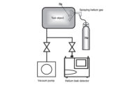
This first method performs leak testing by using the external pressure method. This method involves pumping air out of the workpiece (test object) to create a vacuum, spraying helium gas onto the outside of the workpiece and detecting if helium enters the workpiece with a helium leak detector. Figure 1 depicts the operating schematic for this mode of operation.
The second method performs leak testing by employing the “sniffer” method. The sniffer method involves pressurizing helium gas from outside the workpiece. Figure 3 depicts the operating schematic for this mode of operation.
There is a third way that an ALT could function. This would be by using the internal method. This method involves injecting helium gas inside the workpiece in a vacuum chamber to create a vacuum, and then detecting whether helium leaks from the work-piece into the vacuum chamber with a helium leak detector. This method can be much more costly than the two previous methods explained above. This is due to the cost of the vacuum chamber. The cost of the vacuum chamber increases with the size of the chamber, and larger chambers can be quite expensive. Figure 2 depicts the operating schematic for this mode of operation.
The refrigeration industry is slowly transitioning to automatic leak testing (ALT systems), but reluctantly because of the increased capital cost(s). In the automotive industry, as previously mentioned, there are numerous components that require leak testing. There are also leak specifications linked to human-life safety that require a very high level of leak tightness. The same is not true for the refrigeration industry. Thus, we have two differing sets of circumstances between the two industries which both require leak testing.


