Ultrasonic Testing of Ductile Iron Castings to Verify Nodularity
Nondestructive ultrasonic testing is an ideal tool to measure the nodularity of cast parts.
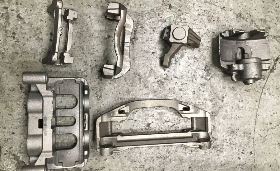
Figure 1: Typical ductile iron automotive castings
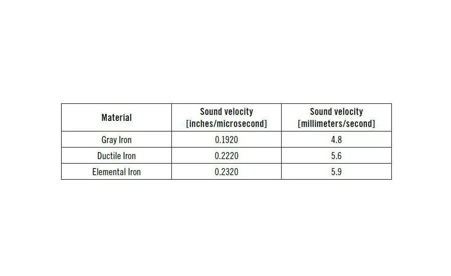
Figure 2: Sound velocity values for cast iron
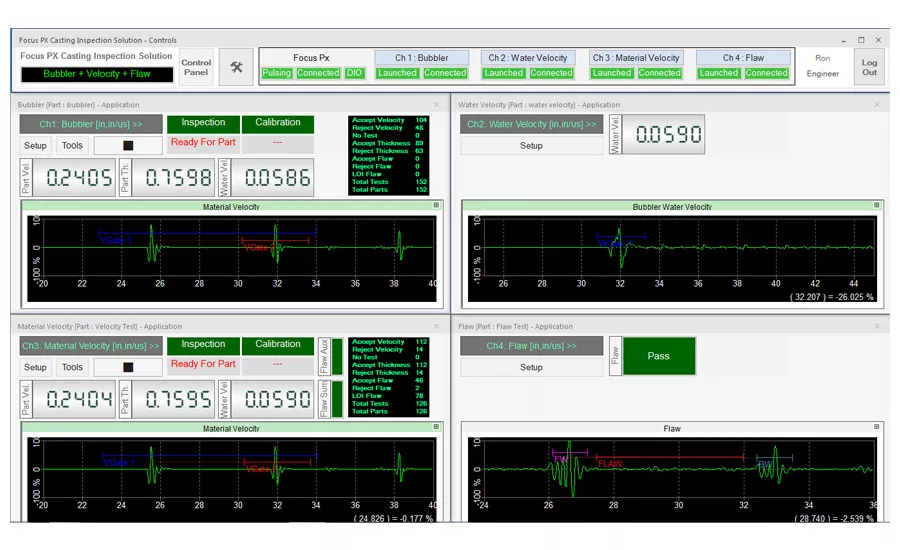
Figure 3: Ultrasonic testing instrument and adapted software
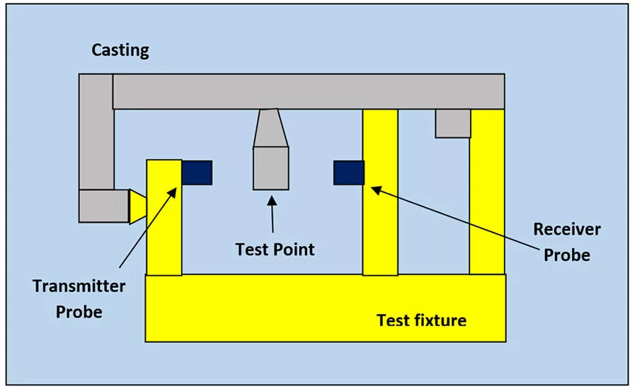
Figure 4: Test setup in an immersion tank
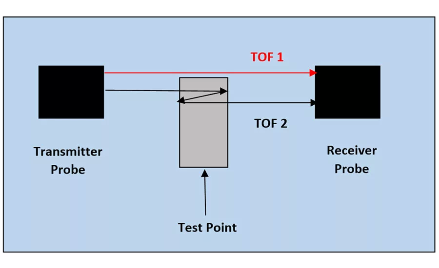
Figure 5: Sound velocity measurement principle
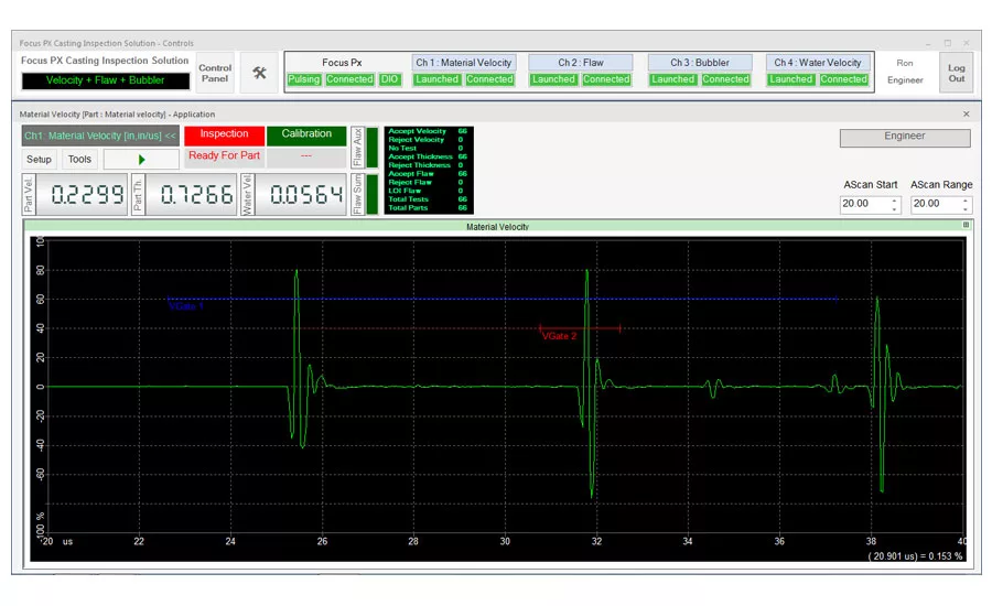
Figure 6: The echoes from the reference casting are resolved and the gate positions are set.
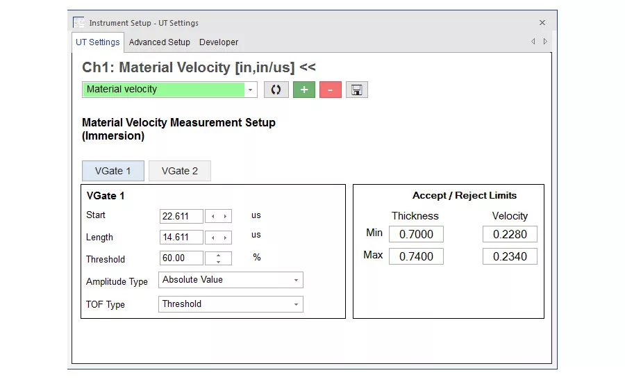
Figure 7: The velocity and thickness limits for the casting to be tested are calculated and entered into the ultrasonic test setting dialogue.
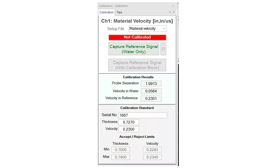
Figure 8: The serial number, thickness, and velocity of the reference casting is entered into the calibration dialogue.
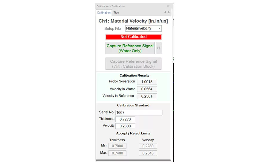
Figure 9: TOF 1 is measured with no casting in the fixture (water only).
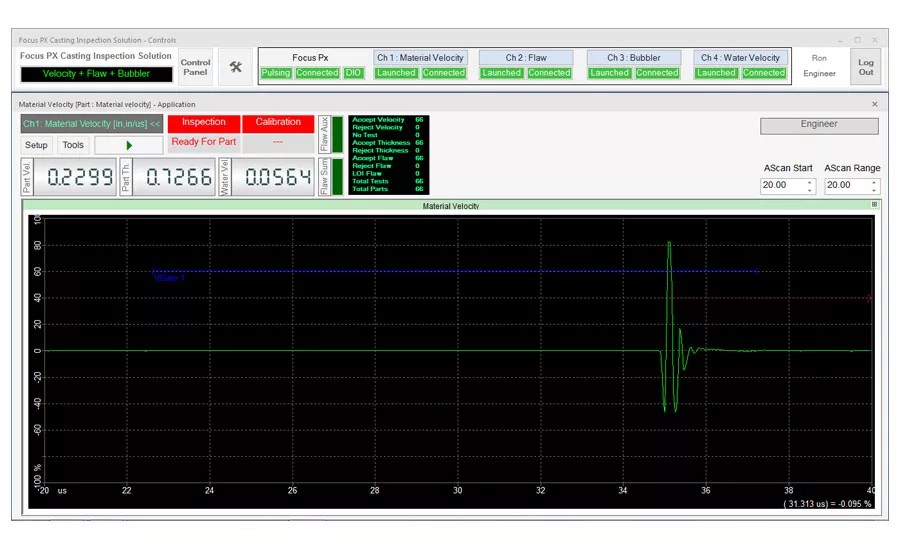
Figure 9: TOF 1 is measured with no casting in the fixture (water only).
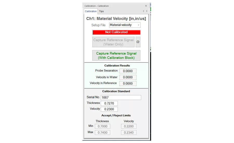
Figure 10: TOF 2 is measured with the casting in position in the fixture.
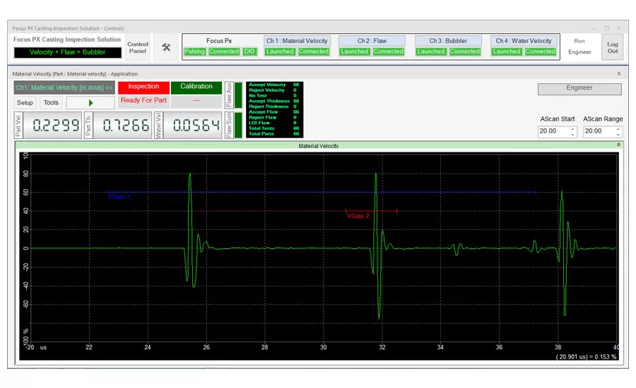
Figure 10: TOF 2 is measured with the casting in position in the fixture.

Figure 11: After a successful adjustment, the measured value is displayed and the system indicates “Calibration OK.”
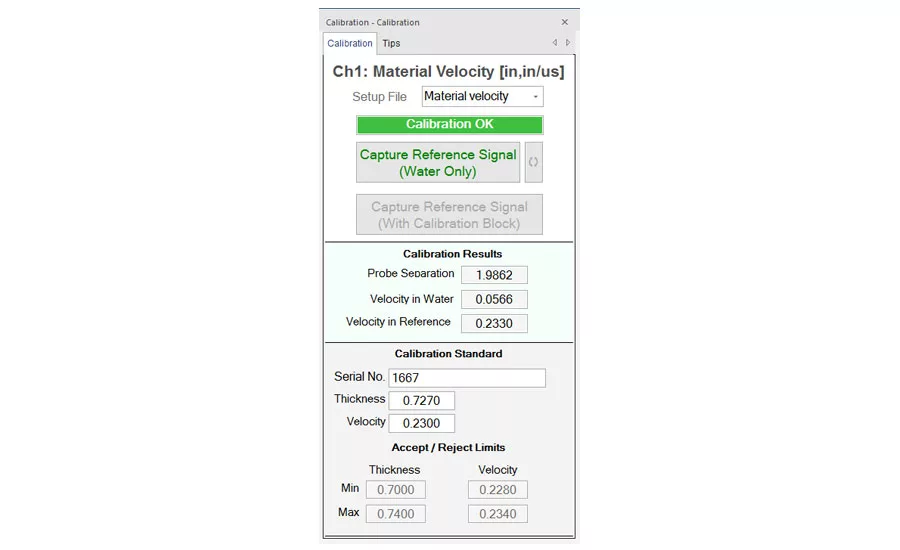
Figure 11: After a successful adjustment, the measured value is displayed and the system indicates “Calibration OK.”
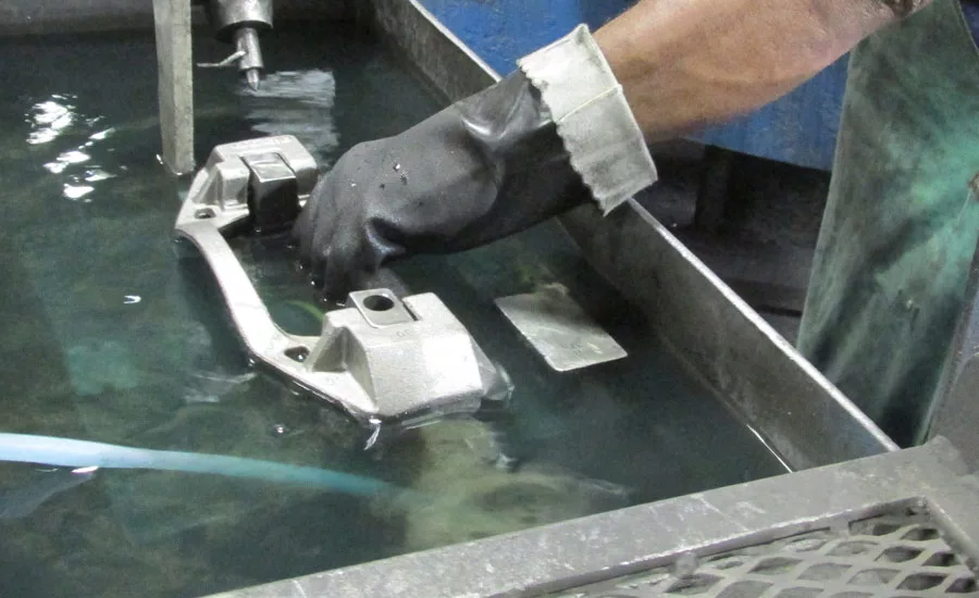
Figure 12: An operator manually loading a casting.
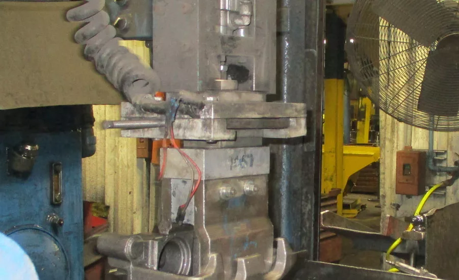
Figure 13: Automated unloading of a casting by a pick-and-place unit.
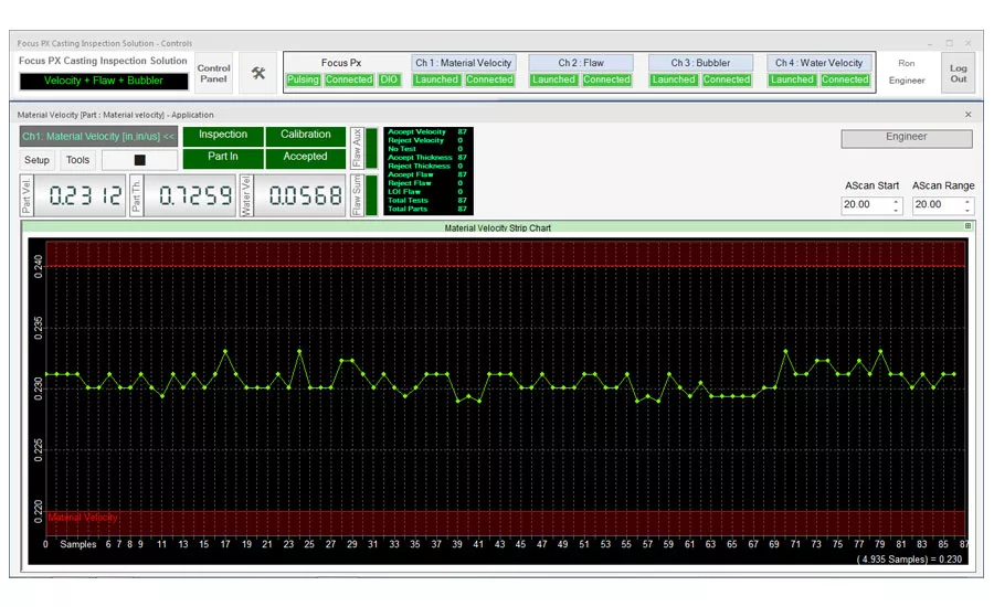
Figure 14: Operator interface showing trend chart, result counters, measured values, and test sequence LEDs.
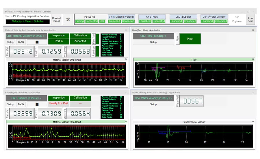
Figure 15: Multi-channel user interface showing four active channels.
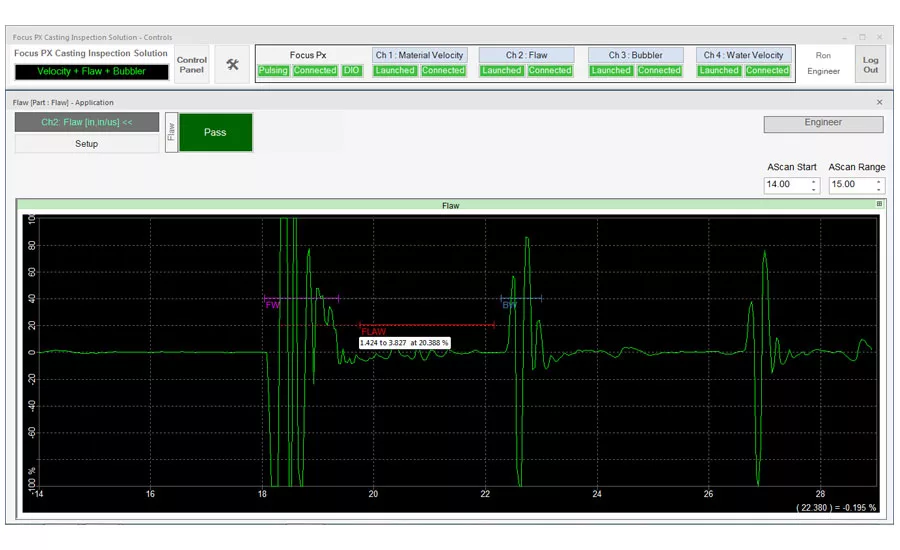
Figure 16: Flaw interface showing lamination test setup.
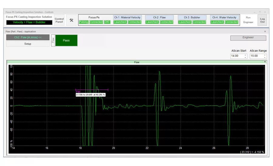
Figure 17: Flaw interface showing interface test setup.
Ductile iron is an iron-carbon casting material whose matrix includes carbon in the form of nodular graphite particles. Rounded graphite nodules in the ductile iron matrix offer greater resistance to stress concentration when compared to graphite flakes (as in gray cast iron) and, therefore, inhibit the creation of cracks.
Safety-critical automotive components cast from ductile iron must be tested to verify that they include the correct percentage of nodularity since catastrophic failure of one of these parts can result in damage, injury, and even loss of life. Manufacturers routinely employ a destructive test method, microstructure analysis, to verify the correct nodularity for sample parts. Microstructure analysis is typically conducted in the metallurgical laboratory and, at best, represents only a small sample of the total production.
Since cast automotive components are used in safety-critical applications, such as in braking and steering systems, nodularity must be verified for every cast component. Because microstructure analysis is a destructive method, this method renders tested components non-serviceable. Consequently, a nondestructive test method is preferred, enabling 100% of the components in a production batch to be tested.
Acoustic (sound) velocity
The relationship between nodularity and acoustic velocity in ductile iron is well known. In general, sound velocity decreases as percent nodularity decreases. Foundries that produce ductile iron castings set sound velocity accept/reject limits to ensure that castings have the required nodularity.
There is a consistent difference in sound velocity between pure iron, nodular cast iron, and gray cast iron. Typically, pure elemental iron has a velocity of approximately 0.232 inches/microsecond (in/µs), nodular iron has a velocity of approximately 0.222 in/µs, and gray iron has a velocity of approximately 0.192 in/µs. Exact velocities for a given application vary depending on alloy composition, grain structure, and other process variables.
Ultrasonic testing
Because of the relationship between sound velocity and nodularity, nondestructive ultrasonic testing is an ideal tool to measure the nodularity of cast parts. The ultrasonic system is adjusted using representative “reference” castings with known nodularity values. The geometry of the reference casting used for reference must be dimensionally representative of the production parts that will be tested.
Accurate ultrasonic measurement of sound velocity requires that the thickness of the reference casting at the measurement point be accurately measured using a micrometer or a caliper. This value is entered into the measurement software and is used to calculate the sound velocity. Accurate velocity measurement is not possible if the thickness at the test point is unknown.
Ultrasonic thickness gages and flaw detectors with a single crystal pulse-echo transducer can be used to manually measure the sound velocity. While manual testing is useful for spot-checking and sorting small batches of parts in a quick sort mode, this technique is relatively slow and subject to operator variability when compared with a dedicated automatic inspection system. Manual testing is neither desirable nor practical for high-volume casting inspection in a foundry processing line.
Automated Ultrasonic Testing Solution
Automated casting inspection in the production line requires a system consisting of an ultrasonic testing instrument, specially adapted software, ultrasonic transducers, and a digital input/output (IO) bus.
In addition to the ultrasonic hardware and software, the system utilizes an immersion tank, precision part number-specific test fixtures, a means to load and unload the parts (loading and unloading can be done manually or automatically by a robot or pick-and-place unit), and a control system to manage the test sequence and separate the castings based on the test results.
The precision part number-specific test fixtures are mounted in the immersion tank and used to position the castings relative to the ultrasonic transducers. Two opposing ultrasonic transducers are configured in pitch-catch (or through transmission) mode; the time of flight between the resulting ultrasonic echoes is measured and the sound velocity is calculated.
The testing location must be an area on the casting where two adjacent flat, parallel surfaces are located. Measurement accuracy depends on repeatable casting geometry and repeatable positioning of the castings relative to the transducers. Mechanical accuracy and the cleanliness of the fixtures is important to maintain accurate test results. Worn fixtures eventually must be reworked or replaced.
The basic principle of the measurement is shown in Figure 5. The ultrasonic time of flight (TOF) between the transmitter and receiver transducers is measured through the water path with no casting in the fixture (Figure 5; TOF 1). Next, the time of flight representing the water path on both sides of the casting plus the time required for the sound to complete one round trip in the casting (Figure 5; TOF 2) is measured. The sound velocity is calculated based on the part thickness and the two measured TOF values.
Because temperature impacts sound velocity, variations in the immersion tank’s water temperature could cause a corresponding variation in the accuracy of the sound velocity measurements. To minimize this effect, the system measures the water velocity after each casting is tested and uses this information to compensate the casting velocity measurement, providing accurate results independent of variations in water temperature. Variations in the temperature of the casting will also have an influence on the measurement accuracy, and if the variation is extreme, system readjustment is required.
The sound velocity measurement system is quickly and easily adjusted (Figures 6–11). Part number-specific test settings can be created, stored, and recalled for later use. Periodic system calibration is required to maintain stability and accuracy. Calibration consists of using a reference casting with confirmed correct nodularity to adjust the system and confirming that the system rejects a second reference casting that has improper nodularity.
Automatic testing
When the adjustment is complete, the system is switched to test mode and production castings can now be tested. The Ready for Test signal on the digital IO bus indicates to the operator or to the mechanical system that the first casting can be loaded. Users can achieve an inspection rate of 15–30 castings per minute with the primary constraint being the loading and unloading of the castings.
One-by-one, the castings are loaded into the fixture in the tank. The software recognizes the presence of the castings based on the ultrasonic echoes that are generated when the casting is loaded and automatically triggers each measurement. The measurements are compared to the preset velocity and thickness limit values, and the system generates an accept or reject decision both as an indication on the screen and as an output signal to the control system. After testing, castings are unloaded from the fixture and separated into accept and reject groups.
During production testing, the testing sequence can be observed via the LEDs on the interface. Ready for part, part in position, and the accept/reject sorting decision are displayed on the LEDs as well as signaled on the digital IO bus. Numeric velocity, thickness, and water velocity measurements are displayed for each tested casting. The measured values for each casting are plotted on a trend chart. Accept and reject parts as well as the total parts tested are counted and displayed by a parts counter on the operator interface. Test results can be exported in a CSV file for offline documentation and analysis.
Multi-channel systems enable multiple measurements on the same casting as well as simultaneous measurements in independent processing lines. With independent channel operation, the operator can stop and adjust one channel while the other channels continue to test.
Flaw Testing
In addition to sound velocity and thickness measurement, it is also possible to dedicate selected channels to perform pulse-echo flaw testing in parallel to sound velocity measurement. Generally, there are two types of flaw tests applied for castings.
Lamination detection is used to detect laminar defects in the cross section of a part using a reject gate positioned between the ultrasonic echoes from the front and back wall from the casting. Castings that exhibit loss of front wall or back wall echo, or positive signals that exceed the flaw gate level, will be labeled defective, and the casting can be rejected.
The casting feature confirmation monitors the position of the front wall echo inside of a preset gate to monitor for casting defects such as short pour (lack of material at a certain casting location) and twist (mechanical distortion of the part). Castings that exhibit loss of the front wall echo will be labeled defective, and the casting can be rejected.
Conclusion
Ultrasonic testing provides a reliable method for measuring sound velocity and, therefore, verifying the nodularity of cast ductile iron parts. Integrating ultrasonic measurement into an automated testing system in a foundry production line enables fast, reliable inspection of 100% of cast production parts. Precise mechanical fixtures are required to help ensure consistent positioning of the castings relative to the ultrasonic transducers. Applications software enables users to easily adjust the system and provides stable, accurate test results. In addition to sound velocity measurement, certain casting flaws can also be detected using dedicated transducers and a dedicated flaw channel.
Looking for a reprint of this article?
From high-res PDFs to custom plaques, order your copy today!


 or manufacturing system")

