Depth Gaging from Top to Bottom
A wide variety of depth gages are available for any application.
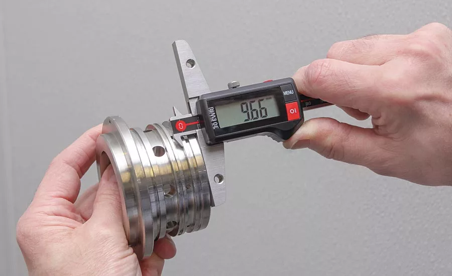
A double hook digital depth gage allows for not only checking the location of a top or bottom surface of a groove but can be used to measure the groove width. Source: Mahr
A depth gage could be as simple as marks on a piece of tape, a line on a ruler, or tape on a drill. Fortunately, of course, modern gages take the guesswork out of measurement, providing a range of simple or high-tech options depending on the job.
In sorting through the wide variety of choices, it might be most helpful to divide gages into two categories: fixed (pin and plug gages) and variable (micrometers, dial indicators, etc.).
“The modern idea of a depth gage is going to be driven by the product,” explains Mike Oddy, technical sales director for Vermont Gage. “Depending on what the output is that you’d like to get, that kind of directs you towards the specific type of design, or gage or inspection tool that you want to use.
Fixed Gages
For the quickest measurement and go or no-go results, there are pin and plug gages. These metal cylinders are manufactured to metrology-grade tolerances to give accurate yet quick benchmarks. Workers can insert the cylindrical plug or pin to check the diameter of a hole. And, if depth is needed, gage makers can machine notches into the side of the cylinder. Notches are typically only put on the go gage, because the no-go’s diameter, by definition, should not fit in the hole. After inserting the pin or plug, if the top of the hole falls between the min and max notches, the depth is correct. If it falls below the bottom notch or above the top notch, it fails. Fixed gages are great for checking high-volume parts that require quick pass-fail tests. It should be noted that there are functional limits for pins with notches. Using a 0.01 inch pin with a notch (assuming the notching operation didn’t damage or weaken the pin), would not be functional because the user would not easily be able to see the notch, Oddy explains.
In some cases, grinding a notch on the end of a pin is not practical because the notch is too close to the face of the gage. The visibility of the notch becomes challenging. Flush pins, which walk the line between fixed and variable gage designs, would be the best tool for the job, according to Oddy. “They are a more functional inspection tool for these shallow or chamfered holes.”
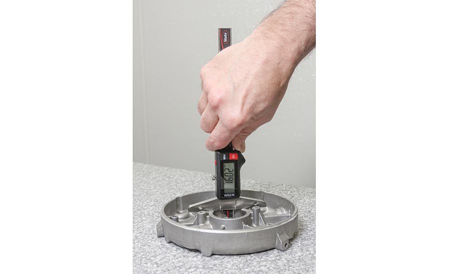
Digital depth gages are a versatile tool for checking depths in a wide range of gaging applications. Source: Mahr
Variable Gages
Variable depth gages include well-known standbys like micrometers, calipers, and dial indicator gages. All will provide accurate measurements, and most gage makers offer digital versions as well. Again, the application will determine which gage is the best choice.
“A caliper gage is most versatile,” says George Schuetz, director of precision gages, Mahr. “So that type of gage tends to be used for incoming inspection, or a general machine shop where they’re running [limited numbers] of different parts and they need something that’s highly variable. They tend to use a caliper type of gage. If it’s a high-volume, tighter-tolerance production facility, they’ll tend to use a comparative depth gage [such as a dial indicator] because it would give them the better performance, and it’s easy for the operator to use.”
Digital depth gages have been available since the ‘90s, and many can now report data directly to a computer workstation wirelessly.
“I think in today’s world there’s more emphasis on liabilities and proving that you’ve done things right and that you’ve tracked your quality, and so forth,” Schuetz says. “So if you can make data collection part of the operator’s measuring process, that’s really no harder than making the measurement, because the data collection is built into the gage.
“Now you can collect data for, maybe, a hip implant. And all of those medical manufacturers, or the aircraft people—any place where there’s a life or death situation involved with the parts—are seeing that data collection is more and more important. It just goes to prove that people have done their jobs and have measured all the parts. I think the long-term trend is that data is becoming so easy to collect, and it’s not a hindrance anymore. That’s going to become a natural part of the measuring process. If you’re going to measure it, you might as well track it and keep the records for it.”
Non-Contact Variable Methods: Vision and Laser Scanning
Some depth measurements can also be performed by vision systems and laser scanning noncontact measurement technology. This can help measure hard to reach places, or in the case of computed tomography, a metrologist could measure the depth of a part’s internal void. All of these technologies fit a broader trend of the increase in 3D modeling, Oddy says.
“There’s a huge push right now in the industry that I’m starting to see—and it’s more coming from a lot of the schools—where many of your engineering folks are coming out with a better understanding of 3D modeling and things of that nature,” Oddy says. “It’s more so than they did even 10 years ago. Now, today, you don’t get many 2D drawings. They’re building it off of a CAD model first, and then they’ll generate a 2D drawing off of the CAD model.”
Oddy says that, as with the case of picking a simple fixed gage versus a variable option, choosing high-tech scanning or vision systems depends on the job. The methods are not necessarily in direct competition with each other. There will always be a place for a quick and manual go or no-go test. Simple economics play a role, as well. With tasks as simple as depth measurement, there must be an extenuating need to choose a five-figure piece of equipment over a plug gage that costs a few dollars.
Looking for a reprint of this article?
From high-res PDFs to custom plaques, order your copy today!


