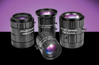
A telecentric lens is often a must from an accuracy perspective. Source: Edmund Optics
With the advent of today’s high-resolution sensors, it is important to understand what performance is needed and therefore, what optics to match with the camera. From 5 megapixel resolution, 2/3-inch format charge-coupled devices (CCDs) to large format area and line scan cameras, different high-resolution sensors require varying high precision optics to optimize performance.
Camera Sensor Landscape
During the past five years, the sensor landscape has grown and evolved substantially. The 0.3 megapixel Video Graphics Array (VGA) resolution was the dominant sensor for many years and is still used in a variety of applications today, predominantly in basic machine vision and the security market. Its successors in many ways were the 1.3 megapixel Super eXtended Graphics Array (SXGA) sensors, which contain more than four times the number of pixels and are widely used on inspection lines. The 1.3 megapixel sensors also have been joined by the 2 megapixel sensors for the higher-end applications of the previous generation.Together those three types of sensors make up the majority of the camera market share and have been sufficient for most needs. With the ever-increasing demands for higher quality products, produced at a faster rate, however, these sensors are only part of the solution to today’s challenges.
The next generation applications require even more resolution to remain competitive in an ever-changing machine vision inspection landscape. To achieve higher resolution, new sensors have added more pixels resulting in a resolution increase of 2.5 to 10X. This increased pixel count allows the system engineer to examine significantly smaller defects, or to detect defects over a larger field of view, resulting in higher part throughput. The release of these standard 4 and 5 megapixel sensors and their subsequent rapid adoption has created a need for lenses that can maximize performance. This need is just now beginning to be addressed.
Cutting-Edge Optics Needed
The previous generations of lenses are optically limited and therefore not able to maximize the performance of the sensor. The situation one wants to achieve in many applications is nearly pixel limited performance, as this allows the operator to get the highest performance from the camera sensor.Higher resolution lenses are needed because while the size of the sensors has remained the same, the size of the pixels has decreased dramatically. This is in order to fit lenses on the same-sized sensors as previous models, whether they are larger or smaller format. The older generation of lenses is not able to pass enough information to the camera to use its full capabilities. Like a signal conditioner in an electrical system, if the lens is not able to pass the optimal information, it becomes the weak link in the system.
For an optical system, the information being transmitted to the sensor is contrast and resolution. The Modulation Transfer Function (MTF) of a lens is a measurement of its ability to transfer contrast at a particular resolution level from the object to the image. In other words, MTF is a way to incorporate resolution and contrast into a single specification.
An easy way to interpret MTF results is to think of imaging a target with black and white lines (100% contrast). No lens-even theoretically perfect-at any resolution can fully transfer this contrast to the image because of the diffraction limit. In fact, as the line spacing is decreased on the target, meaning the frequency increases, it becomes increasingly difficult for the lens to efficiently transfer this contrast. Therefore, as the frequency increases, the contrast of the image decreases. For sensors that have small pixels, one needs the optics to transfer as many line pairs as possible with the maximum contrast so the densely packed pixels can determine the feature to measure. In practice, at least 2 pixels per line pair is needed to achieve a specified contrast and resolution for the system.
Another consequence of the smaller pixel size is the micro-lens arrays on many camera sensors have a more difficult time focusing light onto the individual pixels. The end result is a roll-off of illumination from the center of the image to the corner, resulting in an image with a bright center and dim corners. For any inspection application this will result in inconsistent results.
The good news is that optical strategies can be employed to correct this degradation; however, this requires additional constraints on the optical design of the lens. For example, the lenses must be designed to be close to image space telecentric, which allows the light to come in at an angle of incidence perpendicular to the lens-array, resulting in maximum relative illumination uniformity across the entire sensor.
Choosing a Telecentric Lens
In general terms, a telecentric lens is one that eliminates object-space parallax, or perspective, error. This is a telecentrics’ main benefit and makes integration and analysis much easier in a number of applications. The primary types of applications that benefit from telecentric lenses are inspection, metrology and gaging applications that require measurements to be taken. Using alignment pins on a circuit board as an example, the distance measured using a telecentric lens (the accurate measurement) and a conventional lens can differ by hundreds of microns. In the inspection world, this is simply not an acceptable situation and a telecentric lens is often a must from an accuracy perspective.When choosing a high-resolution camera and telecentric lens pair, there are two options; each has specific benefits that depend on the application. The first option is using a large format telecentric lens with a larger format high-resolution sensor, typically 1-inch format (16 millimeter diagonal) area scan sensors, up to 4K line scan sensors. It is an improvement over the previous generation in that it will offer a resolution increase, a field of view increase, or both. The principal advantage is that a larger field of view offers the ability to inspect more area in the same amount of time, allowing operators to examine more parts side by side, or more area on larger parts. This could decrease inspection time by greater than a factor of 4, potentially quadrupling part throughput and productivity.
The second option is using a smaller format high-resolution sensor-typically 4 to 5 megapixels-of 2/3-inch format or smaller with a high-resolution telecentric lens. This allows for inspecting smaller parts or areas for significantly smaller defects than previous generations. With pixel sizes on the order of 3.45 to 2.2 microns, the resolvable feature size is about twice as small as the current generation of 1.3 megapixel sensors and more than three times smaller than equivalent sized analog sensors. It is also possible to switch to a lens with half the magnification, which would quadruple the viewing area and keep the smallest resolvable feature size about the same as previous generation setups. The lower cost and smaller size of these lenses also make them an attractive option when size and cost are major concerns.
Numbers to the Theory
The best way to illustrate the benefits of going to a higher resolution setup is to show how a current generation setup can be improved. Take a setup with a 1.3 megapixel 2/3-inch sensor and a 0.5X telecentric lens capable of supporting greater than 1.3 megapixels, making the system pixel limited. The resulting field of view would be 0.36 inch² and be capable of theoretically resolving 12.9 microns per pixel.Now take this same system with a 5 megapixel 2/3-inch sensor. If a high resolution 0.5X telecentric lens is used, it will still achieve a 0.36 inch² field, but it could now theoretically resolve 6.9 microns per pixel. One also could put a 0.25X high- resolution telecentric on the camera and achieve a field of view of 1.44 inches² and a resolution that is still close to the original setup.
Operators also could decide to change the system a little more and use a sensor with a 1.2-inch diagonal with 4-megapixel resolution and a 0.5X large format telecentric lens. This will allow one to theoretically resolve 14.8 microns per pixel while viewing 1.44 inches², a full factor of 4 more.
This jump in performance is just one example. If one were upgrading from a small format analog camera with 0.3 megapixel to a large format 4 megapixel camera, throughput could be increased by more than a factor of 12, significantly cutting down the time it takes to inspect parts.
Sensor technology has been making great strides to improve performance through the years and the result is an exciting new generation of high-resolution sensors. While this has created hurdles from an optical design standpoint, the benefits of higher resolution and higher part throughput more than make up for it. As more people begin to purchase these up-and-coming technologies it will drive their prices down and make them the standards for several years to come.
With the tight tolerances and precision manufacturing required, it is more important than ever to make sure that the best optics are chosen to maximize the performance potential of the camera sensors. V&S
Tech Tips
- In general terms, a telecentric lens is one that eliminates object-space parallax, or perspective, error.- Eliminating perspective error makes integration and analysis much easier in a number of applications.
- The primary types of applications that benefit from telecentric lenses are inspection, metrology and gaging applications that require measurements.

Image A: Conventional Lens
Example: Alignment of Jumper Pins
As electronic components become smaller, the degree of precision to align them becomes greater. For this reason, perspective errors in traditional lenses become more troublesome.Image A shows a conventional lens viewing the jumper pins of a typical circuit board at a 45-degree angle. As clearly shown, the lens introduces perspective errors and the angled pins slant toward the center of the field-of-view. Measurements made between these pins for alignment purposes would be inaccurate. Perspective error in this example is 3%, but can be much higher.

Image B: Telecentric Lens
VISION & SENSORS ONLINE
For more information on lenses, visit www.visionsensorsmag.com to read the following:- Machine Vision 101: “Imaging Small Objects”
- “Eliminate Image Distortion”
- “Machine Vision Lighting Demystified”<

