The Shearography Solution
Laser shearography provides a high quality and cost effective inspection solution.
Shearography nondestructive testing has gained wide acceptance during the past decade, providing a number of important and exciting inspection solutions in aerospace, electronics and medical device manufacturing. Originally developed in the mid 1980s for production inspection of composite panels and structures on the B-2 Stealth Bomber, shearography is used to inspect test parts as small as microcircuits to as large as the Bronx Whitestone Bridge. It is used in production for the USAF F-22 Fighter and processing the space shuttle at Kennedy Space Center.
Acoustic shearography-using sound to excite the test part-is the first NASA certified NDT method for the inspection of space shuttle foam to prevent a re-occurrence of the Columbia accident. A shearography camera produces a real-time picture of the test part, showing tiny, submicroscopic dimples and bulges on the surface of a test part when a small stress is applied, revealing subsurface defects.
With sensitivity to 10 nanometers, coupled with a repeatable and quantified stress loading mechanism, a shearography camera can image hidden flaws in composite aircraft panels, cracks in concrete, voids and disbonds in composite ship hulls and even defects in metallurgical bonds in human orthopedic implants. In addition, most racing, truck and aircraft tires are shearography inspected to ensure a safe operating lifetime by culling casings with blisters and belt edge separations.
In the aerospace industry, the critical need to maximize fuel economy and performance have caused engineers to turn to composite laminates and composite sandwich panels with honeycomb or foam cores as well as fuselages built up with filament or tape winding technologies. Traditional methods for nondestructive testing, such as ultrasonic (UT) C-Scan, may not provide the best defect detection capability for these new materials and geometries. Further, UT systems are slow, expensive and require wetting the material to couple the ultrasonic signal. With typical throughput of only 10 square feet per hour, UT C-Scan is becoming a bottleneck for aerospace manufacturers. Further, manufacturing complex composite structures requires a means for fast inspection to provide a process control to ensure quality and reliability at the lowest possible cost. In many aerospace programs today, laser shearography is providing a highly cost effective inspection solution.
As with all NDT methods and technologies, the strength and weakness of the shearography test method must be completely understood, and applications qualified through probability of detection (PoD) verification with written procedures and rigorous training for operators and engineers alike. Once qualified, however, shearography systems can operate with extraordinary efficiency reaching throughputs from 25 to 1,200 square feet per hour, 2.5 to 120 times the typical 10 square feet per hour inspection rate for ultrasonic C-Scan. F-1 race tires can be inspected in a minute. A 100-foot boat can be inspected in a day.
The introduction of the world’s first portable shearography systems came in 1989 to fill an USAF need for field inspection of B-2 honeycomb. These handheld shearography systems vacuum attach to the surface to be inspected. An additional reduction in pressure inside the unit causes slight deformation of the surface where defects are present underneath. These deformations are detected by the miniature shearography camera. Portable vacuum shearography systems have found their way into composite boat and ship testing and have been adapted by the U.S. Navy for the new composite warships. Most America’s Cup racing sailboats are shearographically tested during manufacturing and racing to avoid structural failures.
Throughout the 1980s and 1990s shearography technology improved as lasers became smaller and more powerful, computers improved and costs came down. Production shearography systems have been implemented for numerous aircraft including Cessna Citation X and the Raytheon Premier 1 business jets, the F-22 and F-35. Shearography offers much greater throughput and lower capital cost than ultrasonic C-Scan systems, due to the simultaneous testing over a large area and the fact that the shearography camera can test a structure at an angle, eliminating the need for complex precision contour follow required by UT systems.
When a shearography camera is used to image an aircraft honeycomb panel, a wide range of defects may be seen including disbonds, damage to the core and impact damage. Defects can be measured and locations determined. Interpretation is similar to UT C-Scan, except changes in phase, s/n ratios and other parameters may be used rather than dB changes in UT signal strength. Shearography NDT uses a wide range of stressing techniques to detect defects in materials and structures, including heat, cold, vacuum, pressure mechanical bending, sound, ultrasonic signals and microwaves.
Shearography NDT limitations fall into five categories. The first is the ability to obtain reflected laser light from the test object with sufficient power and uniformity to generate a useful image. Black parts may have so little reflection that the inspection area is small or the resulting image quality is insufficient to evaluate indications. In this case, coating such as dye penetrant developer may be used to enhance the reflectivity of the part.
Second, if the part is highly curved, such as a filament wound tank, an area of high laser light intensity will occur that can cause image saturation. New 12-bit shearography cameras offer a large increase in bandwidth allowing very dark areas and very bright areas in the image to yield good data.
Third, if the part is mechanically unstable, test part motion during the data collection may make the shearograms unusable.
Fourth, the sensitivity of shearography to defects depends on many factors including part geometry, defect area, defect type (embedded foreign material, void or delamination), material stiffness or modulus, and depth below the surface. In general, the deeper the defect below the surface, the larger the minimum detectable size. The evaluation of shearography for a given application must take into consideration all factors affecting the system and operator probability of detection.
Finally, shearography depends on test part deformation to reveal subsurface defects. Elastic materials such as wood, metal and composite materials usually have critical flaw sizes sufficiently large to be detected with shearography methods. Brittle materials such as glass, silicone nitrides and ceramics, however, usually have small critical flaw sizes and are not candidates for shearography inspection.
Within the scope of these limitations, shearography methods have been developed and proven for hundreds of important applications, many of which can use conventional NDT methods.
Portable shearography systems are designed for a range of applications. Some include built-in stressing mechanisms using heat, vacuum or ultrasonic signals while others require an external means of applying stress during the NDT operation. However, all portable systems include a laser illumination source, the real-time image processing computer and a means to support the camera either by tripod or a means to vacuum attach to the surface of the part or vehicle being inspected.
First introduced on the USAF B-2 production program, gantry mounted shearography systems share many operational features with UT C-scan systems. These include: teach/learn part scan programming, electronic image of the entire part, image analysis and defect measurement tools, and automated operation. Shearography systems operate at throughputs typically in the range of 100 to 500 square feet per hour compared to a typical throughput of 10 square feet per hour for UT C-Scan systems.
In addition, shearography scan gantries are considerably less expensive than UT C-Scan systems because precision part contour following is unnecessary. Currently dozens of shearography systems are in operation on aerospace manufacturing programs worldwide. Applications include the Cessna Citation X, F-22 fighter, B-2 and F-16 Global Hawk programs.
Both metal and composite helicopter blades are easily tested in production with either thermal or vacuum shearography methods.
The need for standards for new NDT technologies is driven by the increasing use of composites in aerospace and space applications. In 2007, NASA recognized the need for new, up-to-date consensus standards for the NDT of composites to be applied to the new Constellation Manned Space Exploration program.
Leaders from government, industry users and suppliers in all of the major NDT disciplines, including ultrasonics, radiography, thermography, acoustic emission and shearography developed Standard Practice documents for the NDT of Composites in Aerospace. The Standard Practice for Shearography NDT of Aerospace Composites was one of the first of these new standards published as document ASTM E2581-07 (available from ASTM.org). These consensus documents reflect the level of capability and acceptance to which shearography has achieved.
Shearography NDT is a mature, well-accepted technology used in applications ranging across the marine, electronics, aerospace, tire and rubber industries. Shearography now is included in ASNT SNT-TC-1A and NAS 410 Rev. 3 (1 Mar. 2008).
New consensus standards such as ASTM 2871-07 are providing a consistent methodology in the application of shearography NDT ensuring consistent results. The benefits of the shearography NDT include high throughput and unique solutions to materials and structures that may not be otherwise inspected. NDT
Shearography production equipment is typically one-third to one-half the cost of a C-Scan UT system with the same part size envelope.
Inspection rates are considerably greater, between three and 100 times that for C-Scan UT.
Shearography is a noncontact inspection technique so there is no contamination of the test part.
Shearography nondestructive testing has gained wide acceptance during the past decade, providing a number of important and exciting inspection solutions in aerospace, electronics and medical device manufacturing. Originally developed in the mid 1980s for production inspection of composite panels and structures on the B-2 Stealth Bomber, shearography is used to inspect test parts as small as microcircuits to as large as the Bronx Whitestone Bridge. It is used in production for the USAF F-22 Fighter and processing the space shuttle at Kennedy Space Center.
Acoustic shearography-using sound to excite the test part-is the first NASA certified NDT method for the inspection of space shuttle foam to prevent a re-occurrence of the Columbia accident. A shearography camera produces a real-time picture of the test part, showing tiny, submicroscopic dimples and bulges on the surface of a test part when a small stress is applied, revealing subsurface defects.
With sensitivity to 10 nanometers, coupled with a repeatable and quantified stress loading mechanism, a shearography camera can image hidden flaws in composite aircraft panels, cracks in concrete, voids and disbonds in composite ship hulls and even defects in metallurgical bonds in human orthopedic implants. In addition, most racing, truck and aircraft tires are shearography inspected to ensure a safe operating lifetime by culling casings with blisters and belt edge separations.
In the aerospace industry, the critical need to maximize fuel economy and performance have caused engineers to turn to composite laminates and composite sandwich panels with honeycomb or foam cores as well as fuselages built up with filament or tape winding technologies. Traditional methods for nondestructive testing, such as ultrasonic (UT) C-Scan, may not provide the best defect detection capability for these new materials and geometries. Further, UT systems are slow, expensive and require wetting the material to couple the ultrasonic signal. With typical throughput of only 10 square feet per hour, UT C-Scan is becoming a bottleneck for aerospace manufacturers. Further, manufacturing complex composite structures requires a means for fast inspection to provide a process control to ensure quality and reliability at the lowest possible cost. In many aerospace programs today, laser shearography is providing a highly cost effective inspection solution.
As with all NDT methods and technologies, the strength and weakness of the shearography test method must be completely understood, and applications qualified through probability of detection (PoD) verification with written procedures and rigorous training for operators and engineers alike. Once qualified, however, shearography systems can operate with extraordinary efficiency reaching throughputs from 25 to 1,200 square feet per hour, 2.5 to 120 times the typical 10 square feet per hour inspection rate for ultrasonic C-Scan. F-1 race tires can be inspected in a minute. A 100-foot boat can be inspected in a day.
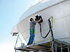
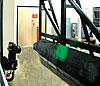
A portable vacuum shearography system inspects a 100-foot yacht for voids and delaminations. Source: Laser Technology Inc.
Shearography History
The electronic laser shearography imaging interferometer was pioneered in the early 1980s by three researchers: Dr. John Butters at Loughborough University in the United Kingdom, Dr. S. Nakadate in Japan and Dr. Mike Hung at Oakland University in the United States. A team led the commercial development of the shearography camera as a tool for nondestructive testing, delivering the world’s first production shearography NDT system to Northrop Grumman in 1987 for the manufacture of the USAF B-2 Stealth Bomber.The introduction of the world’s first portable shearography systems came in 1989 to fill an USAF need for field inspection of B-2 honeycomb. These handheld shearography systems vacuum attach to the surface to be inspected. An additional reduction in pressure inside the unit causes slight deformation of the surface where defects are present underneath. These deformations are detected by the miniature shearography camera. Portable vacuum shearography systems have found their way into composite boat and ship testing and have been adapted by the U.S. Navy for the new composite warships. Most America’s Cup racing sailboats are shearographically tested during manufacturing and racing to avoid structural failures.
Throughout the 1980s and 1990s shearography technology improved as lasers became smaller and more powerful, computers improved and costs came down. Production shearography systems have been implemented for numerous aircraft including Cessna Citation X and the Raytheon Premier 1 business jets, the F-22 and F-35. Shearography offers much greater throughput and lower capital cost than ultrasonic C-Scan systems, due to the simultaneous testing over a large area and the fact that the shearography camera can test a structure at an angle, eliminating the need for complex precision contour follow required by UT systems.
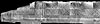
Helicopter blade disbonds and crushed core areas are imaged with shearography. Source: Laser Technology Inc.
How It Works
Shearography cameras have a built-in laser or an external laser light source to illuminate an area on the test part. Fields of view can range from several square inches to several square yards, depending on the maximum allowable defect size. The laser light reflects from the surface of the test part and enters the shearography camera aperture. A beam splitter and two mirrors are used to create two separate images of the test area, which are combined on a CCD detector. The position of one image with respect to the other image can be adjusted in any direction or amount. These “sheared” laser illuminated images interfere with each other and are referred to as an interferogram. The amount and direction of the image shear offset is referred to the shear vector and determines the sensitivity of the shear camera to changes in shape on the surface of the test part. The shearography camera is a common path interferometer and images the first derivative of the out-of-plane deformation of the test part surface in response to a change in load.When a shearography camera is used to image an aircraft honeycomb panel, a wide range of defects may be seen including disbonds, damage to the core and impact damage. Defects can be measured and locations determined. Interpretation is similar to UT C-Scan, except changes in phase, s/n ratios and other parameters may be used rather than dB changes in UT signal strength. Shearography NDT uses a wide range of stressing techniques to detect defects in materials and structures, including heat, cold, vacuum, pressure mechanical bending, sound, ultrasonic signals and microwaves.
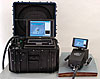
A small portable thermal stress shearography system detects impact damage to composite aircraft. Source: Laser Technology Inc.
Benefits and Limitations
Shearography offers advantages over conventional nondestructive techniques. First, the cost of production equipment is typically one-third to one-half the cost of a C-Scan UT system with the same part size envelope. Second, inspection rates are considerably greater, between three and 100 times that for C-Scan UT. Third, shearography is a noncontact inspection technique so there is no contamination of the test part or water to dry. Fourth, shearography allows the operator to precisely determine defect size, area and location immediately on the test part. Finally, at 400 hours, the operator experience time required to qualify under NAS 410 rev3 is one-third that for UT.Shearography NDT limitations fall into five categories. The first is the ability to obtain reflected laser light from the test object with sufficient power and uniformity to generate a useful image. Black parts may have so little reflection that the inspection area is small or the resulting image quality is insufficient to evaluate indications. In this case, coating such as dye penetrant developer may be used to enhance the reflectivity of the part.
Second, if the part is highly curved, such as a filament wound tank, an area of high laser light intensity will occur that can cause image saturation. New 12-bit shearography cameras offer a large increase in bandwidth allowing very dark areas and very bright areas in the image to yield good data.
Third, if the part is mechanically unstable, test part motion during the data collection may make the shearograms unusable.
Fourth, the sensitivity of shearography to defects depends on many factors including part geometry, defect area, defect type (embedded foreign material, void or delamination), material stiffness or modulus, and depth below the surface. In general, the deeper the defect below the surface, the larger the minimum detectable size. The evaluation of shearography for a given application must take into consideration all factors affecting the system and operator probability of detection.
Finally, shearography depends on test part deformation to reveal subsurface defects. Elastic materials such as wood, metal and composite materials usually have critical flaw sizes sufficiently large to be detected with shearography methods. Brittle materials such as glass, silicone nitrides and ceramics, however, usually have small critical flaw sizes and are not candidates for shearography inspection.
Within the scope of these limitations, shearography methods have been developed and proven for hundreds of important applications, many of which can use conventional NDT methods.
The Cobra helicopter blade mounted in a shearography test is inspected for disbonds, voids, entrapped water and damage. Source: Laser Technology Inc.
Shearography NDT Systems
Shearography NDT systems are for either portable or fixed production applications. Portable shearography systems can be tripod mounted or configured for on vehicle field inspection. Fixed production systems may use test chambers to allow vacuum stress and scan gantries to inspect large panels or structures. As with all laser devices, exposure of the operator to laser emissions must be controlled and shearography instruments and systems must comply with state and federal laws regarding radiation health.Portable shearography systems are designed for a range of applications. Some include built-in stressing mechanisms using heat, vacuum or ultrasonic signals while others require an external means of applying stress during the NDT operation. However, all portable systems include a laser illumination source, the real-time image processing computer and a means to support the camera either by tripod or a means to vacuum attach to the surface of the part or vehicle being inspected.
First introduced on the USAF B-2 production program, gantry mounted shearography systems share many operational features with UT C-scan systems. These include: teach/learn part scan programming, electronic image of the entire part, image analysis and defect measurement tools, and automated operation. Shearography systems operate at throughputs typically in the range of 100 to 500 square feet per hour compared to a typical throughput of 10 square feet per hour for UT C-Scan systems.
In addition, shearography scan gantries are considerably less expensive than UT C-Scan systems because precision part contour following is unnecessary. Currently dozens of shearography systems are in operation on aerospace manufacturing programs worldwide. Applications include the Cessna Citation X, F-22 fighter, B-2 and F-16 Global Hawk programs.
Both metal and composite helicopter blades are easily tested in production with either thermal or vacuum shearography methods.
Standards and Certification
In 1993, the American Society for Nondestructive Testing (ASNT) initiated the Laser Methods Committee to develop certification requirements for shearography system operators. The shearography method was later adapted into the ASNT document SNT-TC1A for Level II and Level III. Since 1995, more than 300 NDT professionals have received shearography NDT training to ASNT Level II. The technology reached a fundamental milestone in industry acceptance with inclusion in ASNT SNT-TC1A for Level III Shearography Certification in 2005 and this year it was included in NAS 410.The need for standards for new NDT technologies is driven by the increasing use of composites in aerospace and space applications. In 2007, NASA recognized the need for new, up-to-date consensus standards for the NDT of composites to be applied to the new Constellation Manned Space Exploration program.
Leaders from government, industry users and suppliers in all of the major NDT disciplines, including ultrasonics, radiography, thermography, acoustic emission and shearography developed Standard Practice documents for the NDT of Composites in Aerospace. The Standard Practice for Shearography NDT of Aerospace Composites was one of the first of these new standards published as document ASTM E2581-07 (available from ASTM.org). These consensus documents reflect the level of capability and acceptance to which shearography has achieved.
Shearography NDT is a mature, well-accepted technology used in applications ranging across the marine, electronics, aerospace, tire and rubber industries. Shearography now is included in ASNT SNT-TC-1A and NAS 410 Rev. 3 (1 Mar. 2008).
New consensus standards such as ASTM 2871-07 are providing a consistent methodology in the application of shearography NDT ensuring consistent results. The benefits of the shearography NDT include high throughput and unique solutions to materials and structures that may not be otherwise inspected. NDT
Tech Tips
Looking for a reprint of this article?
From high-res PDFs to custom plaques, order your copy today!


