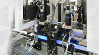
Not only is modern manufacturing increasing production speeds, but machine vision is being applied to ever more demanding applications that were not feasible before today’s high-speed components became available.
We should begin with an exploration of what is meant by “high-speed” when used to describe machine vision. There is no objective criteria that distinguishes a high-speed vision system.
TECH TIPSIn selecting the camera, there are several factors to be considered: image resolution, sensor design, region-of-interest, exposure time, and interface. A common error in machine vision application is to select a camera with higher image resolution than is required by the application. When the available image resolution is greater than needed, use a region-of-interest in the camera to reduce the image data transmitted and processed. |
Speed can be measured as the sustained rate at which a vision system can acquire images (e.g., 100 images per second) or the time between the trigger signal and the outputs being valid (e.g., 10 msec.). Because image acquisition and image processing can overlap, it is possible to have a significant difference in timing between these two measurements.
Also, if a vision system is used on a production line that is considered high-speed, the vision system inherits the designation as high-speed. Of course, if the vision system performs its function as fast as or faster than any other vision system, then by comparison, it is a high-speed vision system.
In the simplest terms, high-speed machine vision requires a short exposure time for the camera, fast data transfer between the camera and the image processor, sufficient, often very high, processing power, and the simplest possible image processing program.
High-speed machine vision starts with the design of the application. The design goal is to make the application programming the least complex. Part presentation is a big part of the simplification. The fewer the number of parts in the image, the faster the image processing will be. Likewise, the less variation in part pose, the uncertainty in translation and rotation, the more efficient image processing will be.
To achieve high-speed performance, the design of the illumination can be critical. An adequate level of illumination can ensure that the camera’s exposure can be as short as practical. A high level of illumination also helps to mitigate the effects of ambient illumination which, in machine vision, is a source of noise. Reducing the contribution of ambient light to negligible levels is essential for the least complex and fastest image processing.
The illumination direction is critical to ensure high contrast between the features needing imaging and their background. Low contrast makes the vision process more vulnerable to variations in parts and their pose as well as to noise, and often necessitates additional image processing. Careful design of illumination direction reduces image variations due to shadows or textures that can complicate image processing.
Finally, ensuring illumination uniformity eliminates the necessity for compensation for illumination variation in the image processing software.
In selecting the camera, there are several factors to be considered: image resolution, sensor design, region-of-interest (ROI), exposure time, and interface.
A common error in machine vision application is to select a camera with higher image resolution (rows and columns of pixels) than is required by the application. This excess image resolution generates a higher volume of image data than needed and places unnecessary time burdens on image transmission from the camera to the processor as well as image processing time. When the available image resolution is greater than needed, use a ROI in the camera to reduce the image data transmitted and processed.
To implement an ROI with a CCD camera, use partial scanning to exclude unneeded rows of pixels from the acquired image. For a CMOS camera, implement a ROI by excluding both rows and columns of pixels that are unneeded.
Generally, CMOS image sensors have higher speed potential than CCD image sensors. Historically, CCD sensors have been more sensitive and have had less noise than CMOS sensors.
Some image sensors, more commonly CCD, the pixel array is divided into two, four, or more parts, each part having its separate output called a tap. Thus, the image sensor facilitates a camera with a two, four, or greater increase in image data transmission speed over a single tap image sensor.
A short exposure time helps increase a vision system’s speed. However, a short exposure time demands some combination of higher camera sensitivity, a higher illumination level on the camera’s field-of-view, or a wider lens aperture that affects other attributes such as depth-of-field and resolving power.
Today’s machine vision camera technology has a rich selection of high-speed digital camera interface standards that can satisfy almost any need. The more common interface standards, GigE Vision and USB3, give image data transfer rates of 100 and 330 Mpixels/second respectively for 8 bit pixels. While these interfaces are good for most general purpose machine vision and don’t require a frame grabber, higher speeds generally require Camera Link, Camera Link HS, or CoaxPress. These interfaces are capable of up to 640; 2,100; or 3,600 Mpixels/second respectively for 8 bit pixels. These last three interfaces require a frame grabber installed in the image processing computer. Each of the interfaces has other attributes such as cable length that ranges from five meters for USB3 to 100 meters for GigE and CoaxPress.
In the past, interface boards used the PCI bus. Because a bus is shared among a number of devices, the camera interface needed to wait to receive control of the bus. This added additional latency that slowed down the process. Modern frame grabbers use a PCIe (PCI Express) connection that provides the board with direct access to memory that is always available. Any camera interface used for high-speed work should use the PCIe interface.
The options for image processing hardware range from a PC or embedded computer to a PC augmented with a specialized processor to an array of specialized high-speed processors. It is possible to review these options in general, but the range of options is quite great. The rate at which image data is received and the amount of image processing necessary to reach an output dictates the optimal architecture.
Hardware and Software
Image processing has two facets: hardware and software. Let’s look at hardware first.
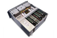
The simplest hardware configuration is a PC or embedded processor. With advances in processing power over the last decade, these processors can handle up to 100 images a second if the image resolution is low and the processing requirements are very simple. As the image data grows or the processing becomes more complex or if the processor must be shared among other tasks, it becomes necessary to add additional processing power. The most common way is to add a processing element such as a GPU (graphics processing unit), FPGA (field-programmable gate array), DSP (digital signal processor), or a second embedded general purpose processor. These processing devices can be added on plug-in boards or they are often available installed on frame grabbers.
For applications demanding extremely high speed, use an array of processors. These can be stand-alone processors or they can be processors on boards that plug into a PC. There are different ways to configure the processors. One way is the round-robin approach in which each incoming image is directed to an idle processor that performs all processing on that image. Another approach is segmented parallel processing where each processor processes a portion of an incoming image. The segmented approach is very difficult to implement. A third approach is to use the processors in a serial pipeline where each processor handles a portion of the processing on the entire image before sending its result on to the next processor in the pipeline.
Finally, the application needs image processing software. While writing the image processing software from scratch offers the potential to optimize the performance for speed, it requires significantly more expertise and work than using a commercial image processing library. Writing software from scratch is best left for those applications that are based on unique R&D for performance.
In choosing a software library, check that it supports the processing architecture and the processors chosen. Make sure that it uses the processor’s vector processing capability for highly parallel computational power (e.g., SSE for Intel processors) and that it supports any specialized processors contemplated (e.g., GPU). Finally, run benchmarks on candidate software libraries to ensure the one you select is best suited to meet your functional and speed needs.
To summarize, here are the critical steps in high-speed machine vision design:
Simplify the part presentation
Provide a high level of illumination
Design the illumination direction to give high contrast and reduce noise
Ensure illumination uniformity
Use only the image resolution needed, apply a ROI in the camera if necessary
Choose the camera interface to support the needed image data transmission capacity
The camera interface should use the PCIe connection in the processor
Supplement the main processor with a GPU, FPGA, or DSP to boost processing horsepower
For extremely demanding applications, plan on using an array of processors
Use a software library rather than code from scratch unless the image processing is based on unique R&D
Run benchmarks on several software packages before making a selection


