Machine Vision Systems Design: The Basics
Systems integration is the process of bringing together diverse and disparate components and sub-systems and making them function as a single unified system.
You’ve learned about light sources, lenses, cameras, camera interfaces, and image processing software. Now, you may be wondering exactly how to design and implement a complete, successful machine vision system. In this article we’ll discuss the general parts that make up the broad task of machine vision systems integration, then focus on a step-by-step process for system design using real-life examples of basic machine vision applications.
Fundamentally, “systems integration” is the process of bringing together diverse and disparate components and sub-systems and making them function as a single unified system. The steps, phases, and terminologies in a successful integration vary widely.
For the overall systems integration process in machine vision the steps might include:
Part 1 – Preparation: Preliminary analysis and project requirements specification.
Part 2 – Design: Detailed final technical/system specification.
Part 3 – Implementation: Assembly/build/initial testing
Part 4 – Deployment: Delivery/installation/startup and acceptance testing.
For this discussion, however, we will focus exclusively on the very critical and sometimes complex “design” phase and how it leads into an “implementation” phase.
Basic machine vision systems
design and implementation
Here is a basic sequence for design in order of execution:
- Select the camera
- Select the lens
- Select the light source
- Acquire some images to verify the imaging
- Select the computer (not required if using a smart camera)
- Develop the program (image processing, operator interface, etc.)
- Combine everything together and start testing and refining
Before starting your design, you need to already have a fully-vetted “requirements specification” that identifies what the system must do and how it will function, an “acceptance test” document that details how the system will be validated, and sample parts for testing. There should be an appropriate evaluation performed in advance to confirm that the proposed machine vision concept and components will be capable meeting the needs of the requirements.
It’s important also to recognize that integration in any discipline is a team activity. In machine vision, it starts with the customer and the integration team (inside or outside of your company). The integration team must have skills in optics, lighting, electronics, controls, programming, mechanical design, and project management and perhaps others like robotics, motion control, documentation, and training.
Given all of these are in place, it’s time to move into system design starting with component selection.
System design: Component Selection and Specification
Camera Selection
We’ll use the term “camera” to broadly describe the component in the machine vision system that performs image acquisition. Basic camera specification is driven by requirements for object/feature detection, identification, location, or measurement and the speed of the process (along with a few other considerations). From the requirements, you determine the required spatial resolution, image resolution, and frame rate needed for your application.
Spatial Resolution
Determine spatial resolution either by the number of pixels that must span the smallest feature that must be processed, or the measurement precision/repeatability that must be achieved, or both.
Say that, from the specification, you need to detect a small hole that is 0.3mm in diameter. Theoretically, two pixels is sufficient, but experience shows us that just two pixels are not reliable. Three, four, or more, pixels need to span the feature. This is a judgement you make. If you say four pixels are required, then your spatial resolution is 0.3mm divided by four pixels or .075 mm/pixel.
In a measurement application, you can likely use a measurement algorithm that gives repeatability of a fraction of a pixel. Exactly how small a fraction of a pixel depends on the size of the feature being measured in the image (larger features can be measured to a higher precision), the contrast of the feature with its background, and the camera noise. The achievable sub-pixel resolution depends on the application. Practical experience indicates the lower limit is around one-tenth of a pixel.
Suppose you need to measure to a precision (repeatability) of 0.01mm and, from experience or some experimentation, you believe the algorithm can be repeatable to one-fifth of a pixel. Then your required spatial resolution is 0.01mm divided by 1/5th pixel or 0.05mm/pixel.
If you have both feature size and measurement requirements, then calculate both spatial resolutions and pick the smaller.
Image Resolution
The required image resolution is simply the number of columns and rows of pixels required to achieve the spatial resolution determined by our calculations. Given a previously specified imaging area (“field of view”/FOV) divide the FOV by the spatial resolution. For example, if we have a 133x133mm field-of-view specified, and a spatial resolution (from our calculations) of .075mm/pixel, then our image resolution is 133mm divided by .075mm/pixel giving 1,733 pixels in both width and height.
Select a camera with pixel row and column count at equal to or greater than what you calculated. In this example you might consider a candidate camera with 2,448x2,048 columns x rows of pixels. In our selected camera we’ll note a pixel size/spacing of 3.45um.
Imaging Rate
The final basic step in camera selection is to verify that the candidate camera can achieve an image frame rate (frames per second) suitable for the specified application and select a suitable interface from camera to processor (not needed with “smart cameras”). Most basic general-purpose machine vision applications have part throughput that is relatively slow (10-15 parts per second and often much slower). The details in implementing high imaging rate applications are beyond the scope of this discussion, but one certainly must be aware that the higher the resolution, the slower the imaging rate. Check that at the targeted imaging resolution the candidate camera and interface will indeed achieve a suitable imaging rate.
Lens Selection
The basic factors that drive lens selection include: the lens format, the desired field of view, the distance the imaging components will be from the face of the object to image (working distance/WD), and the required optical resolution. In our discussion, we’ll be considering selection of a “fixed-focal length” (called “entocentric” or sometimes “endocentric”) lens. (Other more specialized lenses like “telecentric” lenses are useful in many machine vision applications, but that will be for another discussion.) There are three calculations in the specification: optical resolution, the magnification (also called PMAG) and an estimate for the lens’ focal length.
Lens Format
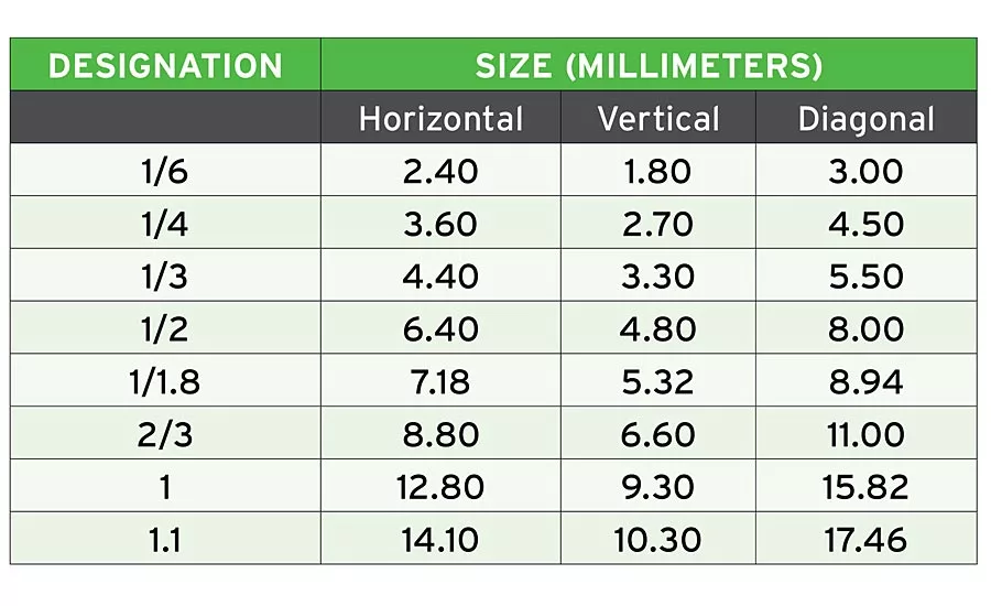
Lenses are design-limited to work with a maximum sensor size, and lens format designations are related to the size of the maximum image circle produced by the lens. The format “titles” are somewhat outdated, and do not match the diagonal size of modern sensors. Use the abbreviated chart included with this article or find a more extensive chart online to match the lens format to the sensor format. In our example, the sensor diagonal can be calculated using the pixel size (3.45um) and sensor resolution (2448x2048) as 11.01mm or a “2/3 inch” format.
Lens mounting also varies by camera and sensor size. The “C-Mount” is very common for low to medium resolution sensors. Note the mounting options available with the specified camera and select the matching lens.
Optical Resolution
This metric helps to ensure that the lens can provide differentiation of small features stated in “line-pairs/mm” (lp/mm). (It’s a good starting point, although there are many other additional measures one can use to compare lenses.) The targeted optical resolution for the sensor is 1 line / (2*pixel size in mm); in our example 1/(2*0.00345) ~ 145lp/mm.
Magnification
An entocentric lens converts or “magnifies” the desired FOV and “projects” it onto the camera sensor. The magnification required for a specific FOV is calculated by dividing the smaller dimension of the FOV by the smallest physical dimension of the sensor. For example, from the discussion above the smaller sensor dimension is 7.07mm, with a FOV of 133mm resulting in a desired magnification (M) of about 0.053x.
Finally, to get an estimate for the lens’ focal length (f) you can use a lens table or a lens calculator from a supplier or the formula:
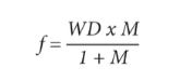
For our example, let’s assume a working distance (WD) of about 500mm resulting in a calculated 25.17mm for the focal length. Our final lens selection then might be 25mm focal length, has an optical resolution of 160 line-pairs/mm, and a C-mount.
Lighting Selection
The goal of machine vision illumination is to create contrast between the part and its background. There is substantial literature on lighting techniques for machine vision and what conditions each technique works well. For example, see “How to Choose a Vision Lighting Technique,” Quality, Sept. 1, 2019, www.qualitymag.com/articles/95666-how-to-choose-a-vision-lighting-technique.
System design: Evaluation and Final Design
Image evaluation and testing
It’s extremely important to prove out your design before committing to build out the complete system. Often during this feasibility test, shortcomings in the design are uncovered and can be quickly remedied before more time and money is invested after which changes are more expensive and time consuming. (From a commercial point of view, some preliminary imaging evaluation of an initial design hypothesis might be done prior to providing a final quotation to a customer, or before committing to an internal end user that the project is feasible.)
For testing, use the actual camera, lens, and light source from the design. Also, use real part samples for imaging that are representative of the variations that will be present in production. If needed, create a mock-up of part presentation that is equivalent to the production environment and includes anticipated presentation variations.
The basic evaluation should achieve the following:
- Verify that the lens and camera produce the correct FOV at the desired WD
- Confirm that the imaging system (camera, lens, illumination) create a high-quality (contrast and feature definition) image relative to the needs of the application.
- Check that the system resolution produces object definition as expected and suitable for the application.
- Evaluate basic processing (defect detection, measurement, etc.) to confirm expected system capability
Of course, throughout the test and evaluation process it might be necessary to re-consider component choices. Where needed, re-evaluate the choice of components to find one that gives a better-quality image.
Computer/Processor
If, for your camera, you selected a smart camera, you have already selected the processor. Otherwise, you can choose a proprietary processor (one that has the processor, a proprietary operating system, and the machine vision software all integrated), an industrial PC, or a standard PC that can work well in some less harsh environments, ensuring that the processor has the interfaces required for the camera and/or other external equipment and the computing power to process the results at the targeted rate.
System Design: Documentation
The final step in the design is to document it. Data that can is collected about the imaging design will help you troubleshoot it and replicate it. A paper covering benchmarking the imaging is available at https://www.autovis.com/images/pdf/resources/imaging-design-benchmarking.pdf and a video is also available at https://www.youtube.com/watch?v=VXq0sPXp978.
Other design considerations
It is indeed rare that a machine vision system is integrated as standalone components. At the very least mechanical design will be required for implementation; possibly the design and build of a complete automation system. Other automation components may be in play as well including PLCs, robots and other devices.
Conclusions
The design phase naturally evolves into implementation: assembly, build, and testing. This is an iterative process, and there will be overlap between design and build phases. During integration, consider one overarching rule: test, refine/tune, repeat. Hopefully this basic introduction to design in machine vision integration will help you succeed in your next machine vision project. The concepts discussed in this article are part of the course work offered in the Certified Vision Professional (CVP) program. For more information on becoming a Certified Vision Professional, visit www.visiononline.org. V&S
Looking for a reprint of this article?
From high-res PDFs to custom plaques, order your copy today!


