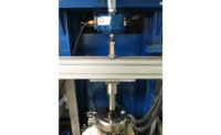
Traditionally, materials testing has been conducted with a device attached to the specimen’s surface to measure the strain. These devices, called extensometers, use very accurate strain gages inside or optical scales. However, despite their extreme accuracy, these devices have three key issues. First, the weight of the device may be enough to bend some specimens, causing errors in your results. Second, there must be sufficient drag force on the specimen to prevent slippage. This is typically applied through very sharp metal contacts called knife edges, which are often sharp enough to cause premature failure in plastic or rubber specimens, giving you low ultimate strength results. Third, the accuracy of contacting extensometers is dependent on sensitive electronics, and the energy released by the break of many materials (especially composite materials or brittle metals) is enough to damage the electronics.
One alternative to contacting extensometers are optical extensometers. Users won’t experience the same grouping of issues as they do with contacting extensometers because optical extensometers do not need to touch the specimen. Therefore, they can’t influence the results of your materials testing and aren’t damaged by the energy released by the failure.
In addition, video extensometers can be used to measure strain at low or high temperatures without the need to place your hands into the temperature chamber to attach the device. The video extensometer can be used to failure, so there’s no need to open the door to remove the device. This allows you to keep the door closed for longer, minimizing the loss of heat or LN2 with every specimen you test and reducing the time you have to wait to get back to temperature.
How Video Extensometers Work
There are a variety of non-contacting extensometer systems available, including some laser-based systems, but by far the most common devices are video extensometers.
The first step to using an optical system is to calibrate the sensor. Cameras measure in pixels, but in order to comply with materials testing standards, you must accurately measure displacements and gage lengths in units of length. To convert the pixels into real length you must present the camera with a calibrated bar in the grips. This bar will have a series of marks on them that are precisely machined to have the same size. The camera will take an image or a series of images of the bar and then correlate the number of pixels between each mark with the known distance between the marks.
The video sensor is now calibrated for this position. However, if you move the camera from this position you must recalibrate because the distance between the camera and the specimen may change, and the relationship between pixels and distance will not be the same. Because of this, a rigid mounting is preferred over movable tri-pod mountings that can be bumped and require re-calibration every time you move.
Before each test with the video extensometer you must place some kind of mark on the specimen, either painted dots or a sticker that is applied to the specimen’s surface. The preferred method is to use paint, because the sticker will not deform with the material underneath and may end up affecting your results.
When your test starts the camera will measure the initial dot separation; this will be used as your specimen gage length. In order for this gage length to be accurate, the specimen must not be bent or curved. One way to prevent this from occurring is to load the specimen with enough force to remove any bending before the start of the test. Most universal testing software allows you to do this with a pre-load. However, if this isn’t available, a manual pre-load will be necessary for the best data.
During the test the camera will take images and calculate the center of each of the painted marks or applied stickers. The distance between the dots will be measured in pixels and converted to a length using the previously attained calibration. This length is then compared to your gage length to measure both the displacement and the strain on the specimen. This calculation takes a small but significant amount of time and the strain data from your extensometer can lag behind the load data from your testing frame. Since the load and strain data need to be properly synchronized for accurate results special steps must be taken. Most systems use a synchronization pulse between the camera and the load frame to correlate the data. These systems are relatively inexpensive and simple to make, but the lag in calculation will make strain control impossible. More advanced systems use specialized electronics that calculate the center of the marks in real time, preventing the need for a synchronization pulse and allowing you to perform strain control.
These devices have been around for a long time, but thanks to advances in optics and the electronics, their accuracy can match or exceed many traditional contacting solutions. In addition, these optical extensometers can be used to perform even more advanced strain measurement techniques, such as Digital Image Correlation (DIC). Thanks to these capabilities, optical extensometers are becoming very common and should be considered for your materials testing system.


