Putting Surface Inspection in the Hands of the Machine Tool Operator
Manufacturers need tools for operators that meet test requirements and are simple to use.
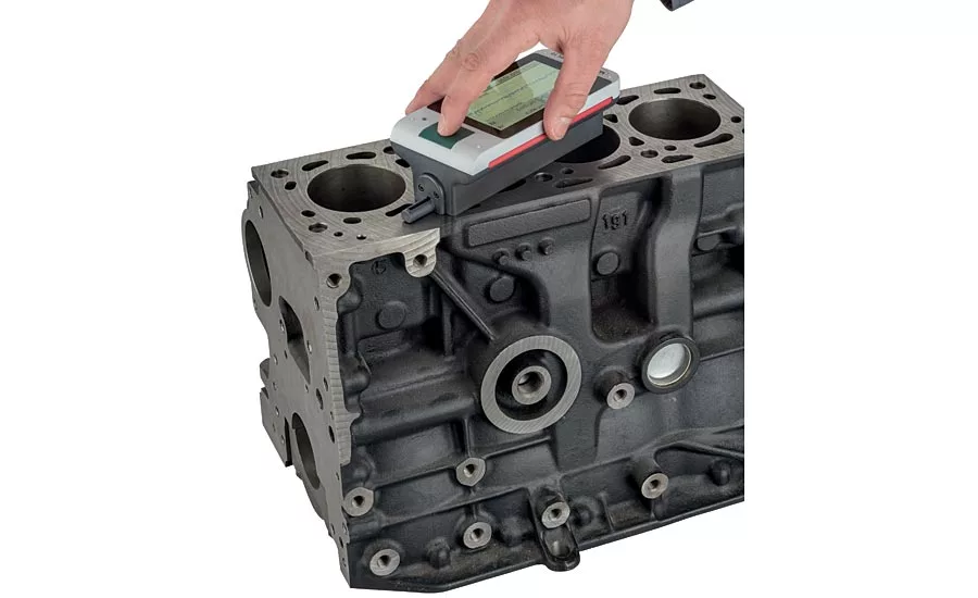
New portable surface finish products make the collection or transfer of measurement results transparent to the user. With each measurement cycle, settings allow for data results to be saved automatically on the device both in data and PDF formats. Source: Mahr
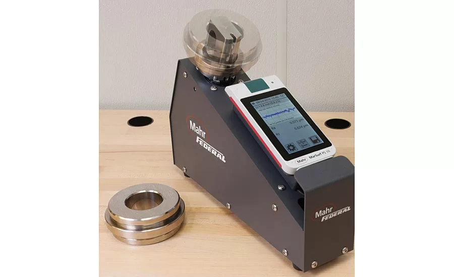
Standard surface finish gages and their remote probes can be incorporated into shop hardened measuring systems. Source: Mahr
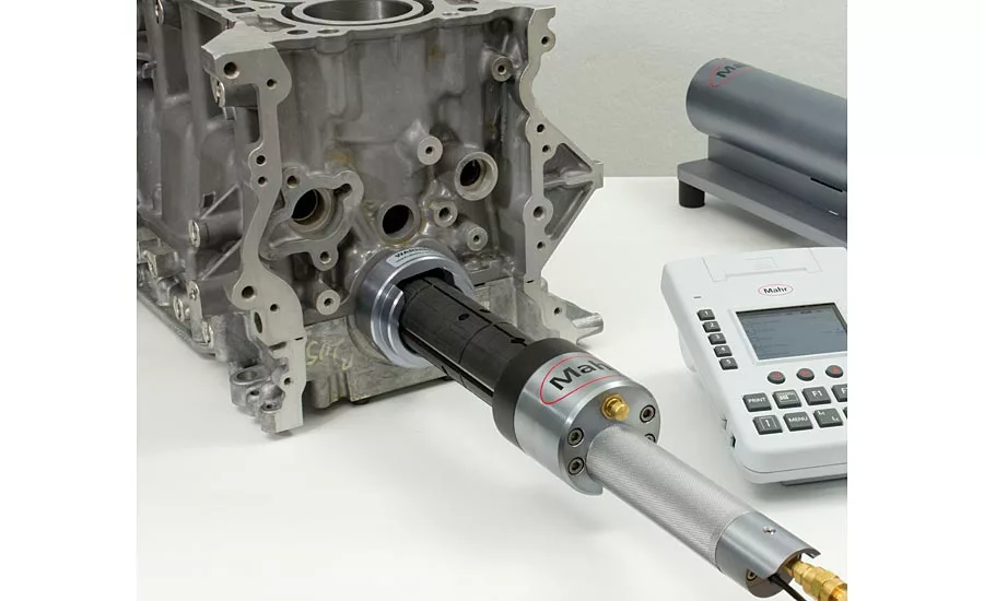
Some bores in the block are not as large as cylinder bores, but also require shop floor surface measurement. Source: Mahr
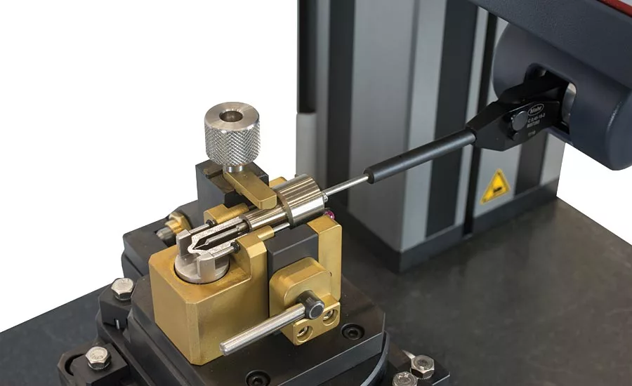
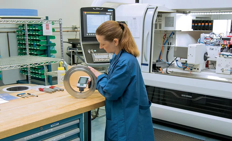
Measurement of various fuel injection nozzle bodies. A fully automatic CNC measuring station enables the measurement of contour and roughness of the entire cone of the nozzle seat, from the blind hole to the guide diameter. Source: Mahr
As part tolerances tighten, both form and surface finish have a bigger influence on the size and function of the product. And with pressures on manufacturing to be more productive, it is no longer viable for checks of surface or form to be performed on a measuring system in a quality room. It’s becoming more important to measure surface finish right at the point of manufacture—often by the same machinist who is manufacturing the part. And while this machinist is often an expert on running the machine, he or she is not necessarily an expert on making surface finish measurements (as well as related tasks like collecting and documenting data).
We have come a long way from the not so distant past when surface finish was “measured” by judgment or compared to a standard with a fingernail. Since the inception of roughness metrology, the number of international standards and internationally recognized surface parameters has increased exponentially. This makes it particularly difficult for new employees (or even seasoned ones) in the quality room or on the production floor to grasp the details and intricacies of surface metrology.
Portable Roughness Gages
Thus, manufacturers need tools for operators that meet test requirements and are simple to use. For example, Ra (Roughness Average) is the go-to method for analyzing surface finish for many applications. Pocket-sized portable surface gages are ideal for these basic measurements. With their small size, robustness and simple one-button operation, manufacturers have been successfully using them for roughness measurements on the shop floor for over 25 years.
But Ra is not the only game in town. How a surface is designed or manufactured often affects how it will perform. Does the surface need minute grooves to hold oil, or just enough roughness to ensure that paint will hold? Does the finish affect the appearance of the surface? There are surface finish parameters available to measure each of these characteristics. And there are portable surface finish gages out there that can measure them. In fact, some newer portable gages can measure more than 30 different parameters.
The difficulty here is that you now have what is basically a laboratory-grade surface finish system in a handheld size. So usability becomes an issue: while measuring multiple parameters can be as simple as pressing a single button, configuring those parameters can be daunting to an operator. Gage makers have tried to stay ahead of this complexity by improving the interface between gage and operator.
Newer Portable Surface Gages: The latest portable surface gages interface with the user just like a smart phone. They require very little training and can be used by the operator in minutes. The units are smart enough to automate filter setting and cut off selection, providing the best results for the user. Also, users can customize the screen and the measurements so they only see the results they need without having to sift through a lot of unneeded information. For fast access to commonly used features the display can be customized to show “favorite” functions such as sending data or accessing specific trace details.
Again like a smart phone, the unit’s display adjusts to allow measurement in any position—horizontally, vertically or upside down—to provide the best viewing angle for the operator.
So, now that the machinist has also become a surface finish inspector he might as well have the tools to become a data collection and analysis expert as well. New portable surface finish products make the collection or transfer of measurement results transparent to the user. With each measurement cycle, settings allow for data results to be saved automatically on the device both in data and PDF formats. At the same time the results can be sent automatically through an output connector (or wireless data transmitter) to a computer for Excel, or third party data collection and SPC analysis. All this is done with just the single start button and no added steps by the user.
Custom or Dedicated Portable Surface Solutions
But even with all this sophistication and ease of use, surface finish measurement on the shop floor can still be problematic. The machine operator may not have the time to closely align the part to the surface finish probe when the land to be measured is very short. He or she may not be able to get deep enough into the bore, or there may be multiple checks called out at specific locations on a cylinder head that require additional set-up. And even if the probe can be brought to the point of measurement, a hurried operator may not be able to protect the probe from being damaged.
Cylinder Bores: Take measuring cylinder bores as an example. Cylinder bores were probably the first application to have dedicated gaging designed for measuring surface finish. Characteristics include bores of various sizes, which can be relatively deep, some up to 8 inches. The prints may call out specific depths and locations for checks, and with up to 12 cylinders in some blocks and four in a vast majority of high volume applications, there are a lot of bores to measure. Therefore the gages need to be highly portable and easy for the operator to align and set to depth. The design also has to protect the sensitive probe so it does not get damaged when bringing the gage to the part.
The dedicated portable surface finish bore gage is much like an expandable tri-bore gage. The tri-bore has a certain amount of size adjustment, but can be set to a specific size. This allows it to “lock” in place and helps provide very repeatable readings with no operator influence. The indicating device is also protected by a transfer mechanism so there are no locating forces applied to it when the gage is placed onto the part.
The surface finish cylinder bore gage borrows the same principles. To give it adjustability to lock into various sizes, interchangeable plates are used to achieve the right measuring range for the diameter. Setting the gage with the right set of blocks allows easy entry into the cylinder bore, and once in place, a manually controlled air cylinder expands the sizing blocks so they lock the gage into position. The clamping force is such that a user can virtually pick up the block with the gage (although this should only be done by serious weightlifters).
But the gage’s cylinder has another even more critical function. When compressed with no air applied, it holds the sensitive surface finish probe in a retracted position. This means that during insertion the probe is protected inside the body of the gage. Once the operator is satisfied with the gage location, he applies the air, locks the gage into position, and the probe extends so he can make the surface test. When done, the air is released, the probe retracts, and the gage becomes free, allowing easy removal by the user.
Small Bores: Some bores in the block are not as large as cylinder bores, but also require shop floor surface measurement. Here another tack can be taken. Again borrowing from the world of precision dimensional hand gaging, a takeoff on the fixed mechanical plug can be incorporated. With this type of gage, the mechanical body of the plug is made to measure a specific bore size. Thus it is fast, self-centering, and there is no operator influence.
The same concept can be used for a portable surface finish gage. In this case, a plug body, made close to the bore size being measured, incorporates a surface finish probe. But unlike a fixed mechanical plug, which always has its contacts touching the bore, the surface finish version keeps the probe retracted until the plug is in its final measuring position. Then a mechanical transfer mechanism releases it.
Other examples of surface gages for automotive parts include crankshafts and camshafts, along with the interrupted bores that they go into. A critical roughness and waviness check includes the deck face of heads and blocks to ensure a good leak-free seal when assembled.
Automated Surface Solutions
But even with the best custom designed tools, the operator may be faced with having to measure more parts and part features than his equipment can handle. Thus, fully automated surface measuring machines are available to take the user influence out of the measurement. There are many examples of where the operator is benefited by not having to try to make these complex checks. Examples can range from large parts—such as an engine block where all the surface checks can be made with one automated setup—to the other extreme where small parts with very small holes need to be measured. These would be difficult if not impossible for a user to try and align the probe to the bore to be measured.
On the large part side, CNC measuring systems are designed for roughness measurement on workpieces such as cylinder blocks and cylinder heads. The positioning of the workpiece and the program sequence is fully automatic, controlling and driving the rotation of the part and instrument in two axial directions, therefore providing high flexibility and accessibility to all of the measuring points.
Multiple probes are available and automatically selected when called for, each using pre-programmed probe tip compensation. This makes it possible to program according to part drawing data while potential deviations in the real positioning are corrected automatically. The measurement process is time-optimized, ensuring the results are presented in a most efficient and time saving manner.
The other extreme are parts with extremely small bores that are very deep. An operator would have to have a lot of experience to get a small probe aligned with the bore and then try to get the probe deep into the bore for the surface check at the bottom of it. And in gaining this experience there would surely be a number of sacrificial probes lost along the way.
An example of this is the measurement of various fuel injection nozzle bodies. A fully automatic CNC measuring station enables the measurement of contour and roughness of the entire cone of the nozzle seat, from the blind hole to the guide diameter. Using a very small probe tip (0.45 mm total height), a blind hole with diameter of up to approximately 0.6 mm can be entered. The customized software routine allows the fully automatic measurement of the entire inner contour of the workpiece.
Probe arms and workpiece holder dimensions are stored in a coordinate system, so that no further setting of the measuring station is required during operation. Using “workpiece recognition” and an automatic probe arm change unit, the degree of automation can be designed to any extent up to completely operator-independent execution. With the “palette measurement” option, the measurement of several identical workpieces can be performed without operator involvement, allowing the system to run lights out overnight to complete the entire pallet.
The benefits of these CNC measuring stations can be summed up as follows:
- Measurement tasks with very tight tolerances on small or large parts
- Fast measurement without complex setup of the measuring station
- Automatic alignment and positioning of workpieces
- Very low risk of probe arm damage due to probe arm check, offset clearing and workpiece control
- In-process measurement
- Statistical evaluation of each feature for controlling the manufacturing process
- Complex and diverse measuring tasks can easily be performed without influence of operating personnel on measurement results
Whether it is single button operation on a handheld portable gage, or a single start button on a full CNC surface gage, surface finish measurement is advancing to and automating at the point of manufacture.
Looking for a reprint of this article?
From high-res PDFs to custom plaques, order your copy today!


