Benefits of Automating the Calibration Process
As with any measurement process, reducing the influence of the human element helps improve the results and reduce the measurement uncertainty.
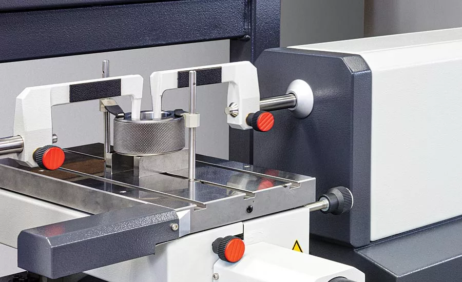
Figure 1: A master ring gage being measured on a high-precision universal length measurement machine with a CNC measurement table.
The precision length calibration process is very much like any length measurement process, but taken to a significantly higher level. Both processes are composed of the same elements, including the following five key parts of any measurement/calibration process:
The Standard: This can be any certified physical dimensional standard used for setting a zero or starting point. Any standard employed in a measurement/calibration process should be recently certified, clean, free of damage/corrosion, temperature stable, and appropriate for that particular measurement process.
The Workpiece: For the measurement/calibration process, this is the measurement artifact being measured/calibrated—it could be a gage block, a dial indicator or any other dimensional reading or artifact. As with the standard previously mentioned, it should be clean, free of damage/corrosion, and temperature stable to the same degree as the standard and the test instrument.
The Instrument: The unit that will be performing the calibration of the workpiece. Whether it be a dial indicator calibrator, a gage block comparator, or a universal length machine, it should have the appropriate design functionality and the required measurement accuracy level as dictated by the calibration process requirements of the workpiece.
The Operator: Since most calibration processes are cost-prohibitive to fully automate, the influence of the individual machine operator is a key part of the measuring process. In the following sections, some tips and tools will be discussed that will make the operator’s job easier, with the goal of reducing the overall influence and associated sources of error.
The Measurement Environment: In the realm of high-accuracy precision length measurement, issues with the measurement environment can contribute a large part to the overall measurement uncertainty. When performing sub-micron dimensional measurements, the temperature must be controlled to parts of a degree at the calibration station. This can be done through long-term temperature and humidity studies of the calibration station area, proper airflow characteristics, the appropriate HVAC system and controls, and the associated financial investment. Sub-micron measurement capability is not for the light-hearted—there is a lot of work related to setting up the proper laboratory environmental controls, which are essential for performing such a high-accuracy task properly.
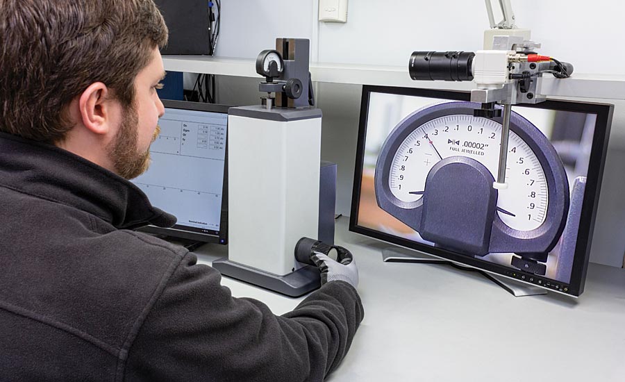
Figure 2: The parallax-reduction camera attached to an indicator-checking machine. The camera captures the dial face of the mounted dial comparator from a consistent position, thereby eliminating parallax error potential between operators.
For the People
The operators performing precision calibration work have a critical function in society. Certified length standards are often used in automotive, aerospace, and medical applications, where they are used to control and certify critical components. Moreover, even outside of these scenarios, calibrated length standards represent an important cornerstone of any company’s manufacturing setup.
Some of these measurement tasks can seem tedious even if they are critical in nature. For example, viewing the analog face of a dial indicator all day long or tapping a master ring for hours to find a reversal point requires significant concentration. Unfortunately, such repetitive tasks can be a human’s worst enemy when consistent quality of work is on the line. As such, any opportunity to reduce or eliminate human variation in the calibration process should be implemented if beneficial.
Some simple operator improvements will be discussed below, followed by solutions that are more complex.
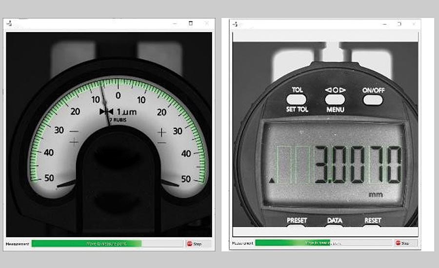
Figure 3: A dial comparator and a digital indicator being tested on an automated indicator-checking machine. The green highlights indicate that the software is recognizing the reading on the scale.
Easy on the Eyes
Dial and digital indicators, and comparators, are in wide use in manufacturing. It is common to have hundreds, or even thousands, of these measuring devices in a large manufacturing facility.
While digital products are gaining traction, there are still many dial indicators in use, which make them subject to a regular calibration cycle. The overall process can be pretty time consuming for the lab technicians calibrating dial indicators. Once mounted in the calibrator setup, the measurement process typically follows a standard process of:
- Move the spindle of the indicator up/in
- Check the reading on the dial
- Record the result
- Repeat until the entire spindle range has been measured.
- Repeat the whole process with the spindle now moving down/out in order to obtain the hysteresis measurement.
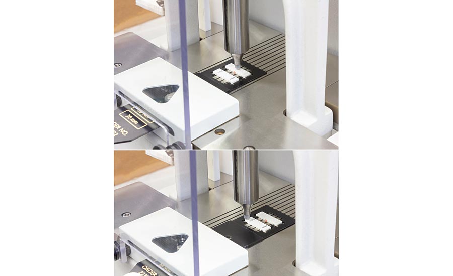
Figure 4: Gage block positioning template in use with a gage block comparator, showing the deviation measurement point of the master block in the top image and the second variation in length (ViL) measurement point of the work block in the bottom image.
A source of error in this measurement process is parallax error in which the user is not looking straight at the indicator but rather at an angle, and thereby not seeing the true reading of the test piece.
In the modern day world of metrology, more options for mitigating parallax error from the measurement process exist without breaking the bank. For example, an inexpensive CCD camera connected to a computer can allow the operator to view the dial from a computer screen, ensuring that each reading the dial is consistent. While this setup can eliminate the occurrence of parallax error from the measurement process, it will not completely eliminate eyestrain, as the operator is now focusing on a computer screen rather than directly on the dial face of the indicator.
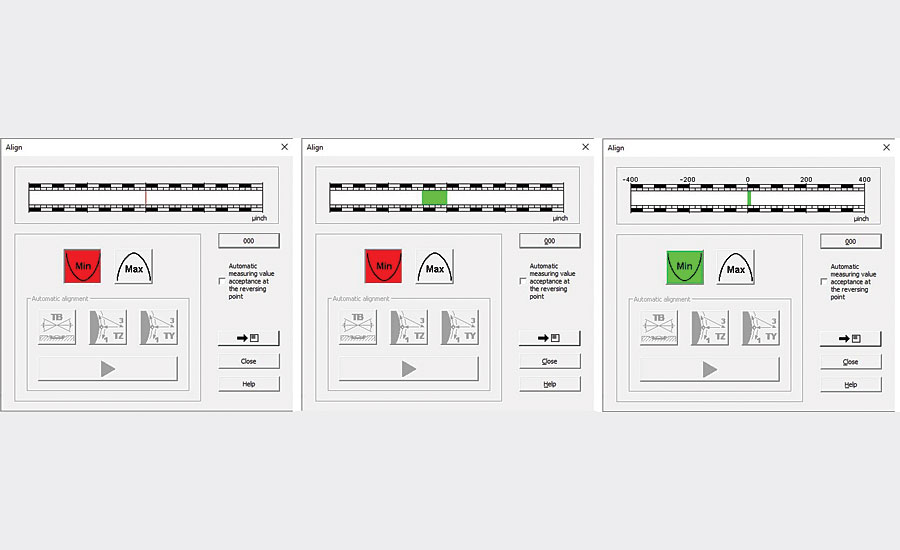
Figure 5: Visual aid used on the universal length measurement system, showing the progression from red to green indicating the discovery of the reversal point.
Fully Automated Dial Indicator Calibration
A further step up from the aforementioned CCD camera would be to integrate that camera into a fully automated dial and digital indicator calibration system. By comparison, this is a more expensive investment but provides a greater return on investment.
The concept revolves around taking the same type of camera mentioned in the previous section and connecting it to software that can actually “read” the different parts of the dial of analog indicators (minor graduations, major graduations, etc.) and/or the digital display of digital indicators. This is combined with a motorized indicator calibrator station and a completely automated indicator calibration system has been achieved.
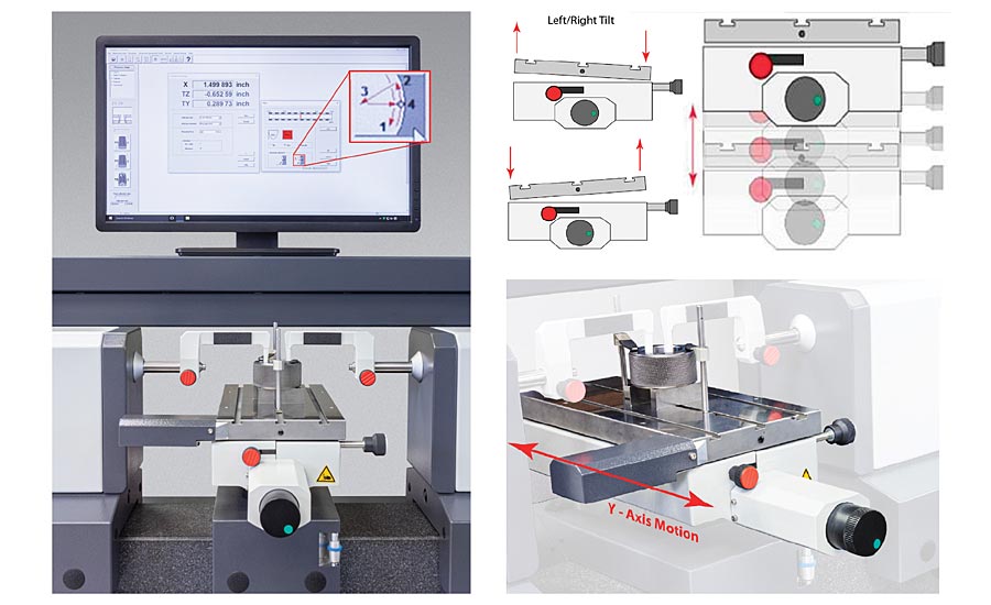
Figure 6: A ring measurement on a universal length measurement machine with a CNC table. In the alignment tool within the software, one of two buttons actuate the CNC table move the ring: (left) tilt side-to-side, (middle) up and down (Z-Axis), and/or (right) front-to-back (Y-axis), as needed, in order to find the reversal point.
Automation Aids for Measuring Gage Blocks
Gage blocks are the ubiquitous setting standard for manufacturing. As such, they must be certified on a regular basis in order to maintain the confidence of that measurement standard.
The measurement process for gage blocks requires a significant amount of the operator’s concentration and hand-eye coordination. Computers have helped automate and reduce operator influence for this measurement task simply by taking away the chance of data-transcription errors.
In today’s systems, computer software automates the process by storing the gage block sets in files where the set number can pull them up, automatically record the measured deviation of the individual gage block and then automatically take into account the correction offsets in order to produce a final report. The software thereby eliminates the possibility of repeated data transcription errors.
Approximately 15 years ago, the standard method for measuring gage blocks changed slightly. Initially, gage blocks were measured by taking a set of readings along the centerline of the block. The change that was implemented moved the measurement points of each gage block to one measurement at the center of the block and four measurements at 2mm from each corner. This not only added extra readings but also put a very stringent location requirement on where to measure the block. Unfortunately, having an operator find a point 2mm from each corner of a gage block repeatably is difficult and can vary greatly between operators.
To aid in compliance, many gage block comparators now incorporate the option of using measurement templates that will position the gage block easily and repeatably to the five aforementioned measurement points that need to be measured (center and four corners).
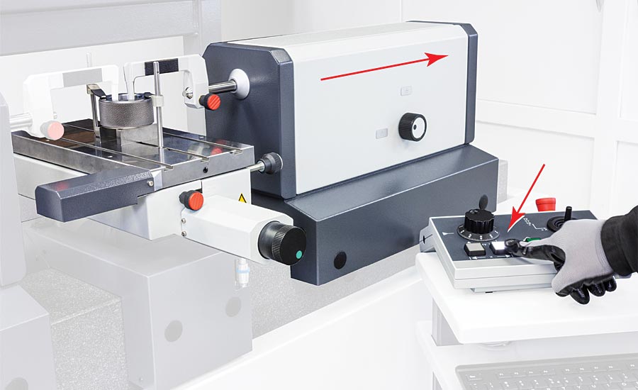
Figure 7: The motor-driven gage head of a high-precision universal length measurement machine, where the gage head is engaged with the push of a single button.
Computer-Aided Techniques for Length Measurement Systems
Second in prevalence to gage blocks is the class of ID and OD masters: master rings, master plugs, and master discs. These master gages are held to extremely tight tolerances and require multiple measurements, ID or OD, in order to obtain a certified measurement.
For many years, master rings and discs were certified on precision ID and OD comparators. These ID and OD comparators were highly-accurately measurement instruments but also labor-intensive. Due to the “comparator” configuration, they required a setting standard to first zero-out the comparator in preparations for the comparative measurement. These master rings and discs are typically manufactured to any specified size using certified gage blocks stacks as the reference point to create the desired diameter. Due to the required high-accuracy of these master gages, a second gage block stack is usually made to verify the first stack’s size.
Once the ID/OD comparator was set up, the user would take the subject ring or disc, place it on the gage between the contact points, and then usually tap the sample back and forth using a small plastic mallet. This would be done to find the min or the max value (i.e. the reversal point) as displayed on the analog dial readout in order to determine the correct reading once the part was properly aligned with the contacts. This process would then be repeated so that six measurements were taken for each part: three levels (top, middle, and bottom) each at 0 and at 90 degrees.
Universal length machines since have taken the place of many of these ID/OD comparators. They offer a longer direct measurement range and a high level of accuracy over that range. So rather than creating two stacks of blocks for every required size ring or disc to be measured, a single certified master ring or plug can now be used to set the system to a specific certified size and the ULM will be able to measure workpieces accurately within its direct measurement range.
While the visual aids are helpful in mitigating operator error in the measurement process, it is still a manual process. For the tightest of measurement tolerances, this level of error mitigation is not sufficient. Further removal of the operator’s influence on the measurement process must be now included, which is an important part of the construction of systems with axis control for measuring diameter.
Computer-integrated measuring systems feature a CNC table onto which the measurement artifact is mounted. Once the operator has placed the part on the table and properly affixed it, the system will automatically perform the required adjustments at the click of a button in the software until the reversal point is found. While the visual-aid-based process is available with CNC-controlled systems, the motorized table eliminates the operator influence from the reversal point search.
As with any measurement process, reducing the influence of the human element helps improve the results and reduce the measurement uncertainty—something to actively consider when delving into the world of critical high-accuracy measurements. Q
Looking for a reprint of this article?
From high-res PDFs to custom plaques, order your copy today!


