Calibrating Standard Threaded Gages
Applications requiring threaded parts come with a variety of performance requirements.
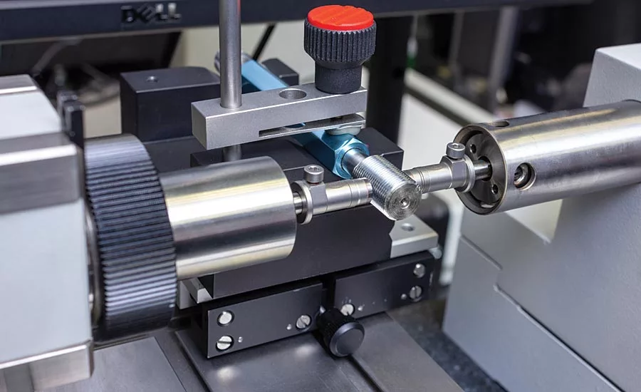
Figure 1: Measurement of the major diameter on a thread plug
Screw threads are one of those important elements of mechanical design that are often taken for granted but find usage in critically important applications. There is a very complex science behind applications of threads—even thinking about it can send shivers down the spine of the most astute mechanical engineer. The large spread of applications requiring threaded parts come with such a variety of performance requirements that one can get lost in some of the principle design functions such as how a threaded part is assembled to a matching part, how a threaded part performs under different operating conditions, and the strength of the threaded components.
As an example, screw threads are composed of many design elements that distinguish them from parts with a plain cylindrical shaft or hole but, in reality, the basic shape of a threaded mechanical element is the cylindrical shaft or hole. While there are many elements involved in checking screw threads, as there are different machines used to verify thread dimensions, most of the verification process comes down to a few critical dimensions, such as pitch diameter and major diameter, that can be measured and certified using master threaded rings and plugs. Just like master gage blocks provide the basis for dimensional measurement, master threaded plug and ring gages are the fundamental tool used to verify that an internal or external thread of a work piece is correct.
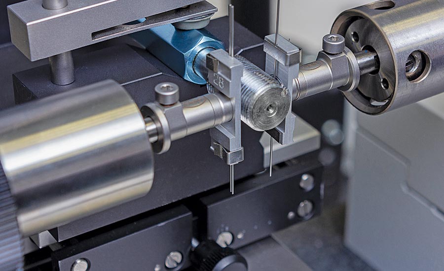
Figure 2: Measurement of the pitch diameter on a thread plug using the “three-wire method”
There are many different types of threads to serve different purposes and many different threaded master gages to certify them. As with any reference standard, these threaded master gages need to be calibrated and certified to understand their critical parameters.
Plain Threaded Plugs
On a straight threaded plug gage, the two most common checks that need to be certified are the plug gage major diameter and the pitch diameter. As with other dimensional standards, there are industry standards that define how thread standards must be calibrated. In this case, ASME B1.3 is the one to reference.
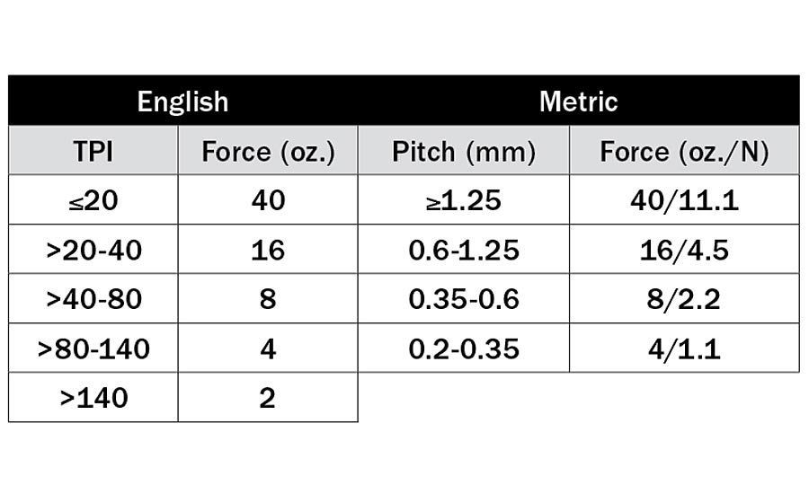
Table 1: ANSI/ASME Recommended Thread Calibration Force by Thread Count/Pitch
The key to any measurement of gage variation is to use a calibration gage and tools with proper geometric contacts that are both accurate and sensitive enough to perform the thread calibration. For a threaded gage plug major diameter, for example, the measuring system must have anvils large enough to span the thread outside diameter (OD) and be parallel enough to reduce the potential of introducing unwanted gage errors. The specification includes additional details about the face of the contacts that specify parallelism of 4.0µ” (0.1µm) or better. The specification also notes that the resolution of the measuring system should be 10µ” (2.5µm) or better. Of course these two callouts alone do not make for a perfect measurement. The gage needs to be checked in an appropriate environment, using proper reference standards and by trained operators (more about this later).
The major diameter is checked by placing the test piece between the reference and sensitive jaw in the gage. In making the measurement, the specification calls out the number of measurements to be made on the threaded plug along with the proper gaging pressure to be used. The gaging pressure is typically the same as is specified when making the second most common check on the threaded plug, the pitch diameter. Ensure the same gaging pressure when making the OD check.
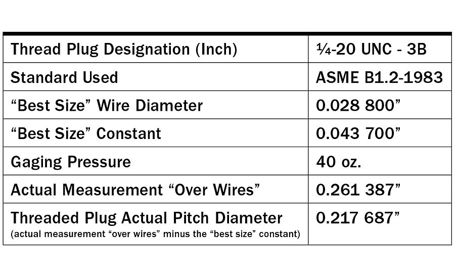
Table 2: Table of Thread Measurement Parameters - Inch
This “three-wire method” is the only acceptable procedure used for checking thread pitch diameter as defined by the ASME specification. Unfortunately, there is no easy and direct technique for taking pitch diameter measurements—but it is the most critical measurement on the threaded plug gage.
The three-wire method provides for locating segments of wire of a known diameter at three places on the thread and using a machine to measure the diameter over the three points of wire. A side note here: the three wires are used because they set up a nice triangle over which the two measuring anvils will sit against. This could be done with two wires if there was a good way of setting the height of each wire to the pitch height and then make a two-point measurement. However, most length measuring machines do not have this and the three wires held in a small holder makes for a fast and accurate result.
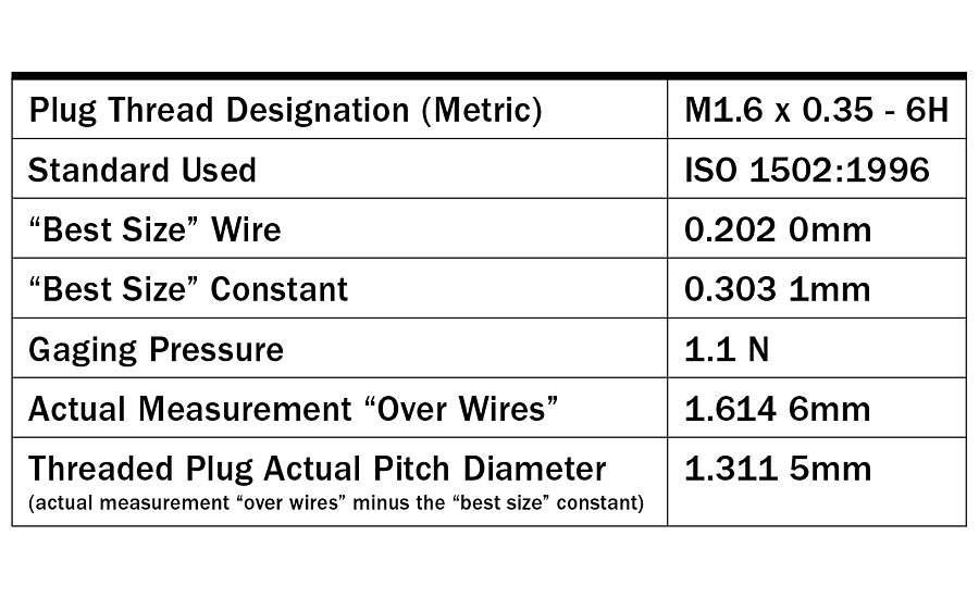
Table 3: Table of Thread Measurement Parameters - Metric
The key to an accurate reading is in selecting the “best size” wire diameter for the measurement. The wires sizes are selected based on the threads per inch and are usually found in a Table of Thread Elements.
Also specified, based on the threads per inch, is the gaging pressure to be used. For example, if the plug has 20 or fewer threads per inch (TPI), a 40 oz. gaging force is required. At the other extreme, if there is a thread count of 140 TPI or more, then only 2 oz. of gaging force is used. On the metric side of the equation, for pitch greater than or equal to 1.25mm, a gaging force of 11.1 N is required. At the other end of the spectrum, if the thread pitch is between 0.2-0.35mm, then the required gaging force is 1.1 N. For the ANSI/ASME recommended calibration force settings based on thread pitch, as dictated by the ANSI/ASME B1.2-1983 (English) and ASME B1.16M-1984 standards, please see Table 1.
To calculate the pitch diameter using the “best size” wire, refer to the Table of Thread Elements to choose both the thread wire size and the “best size constant” which corrects for the diameters of the wires and the amount they protrude from the thread when measured over the wires.
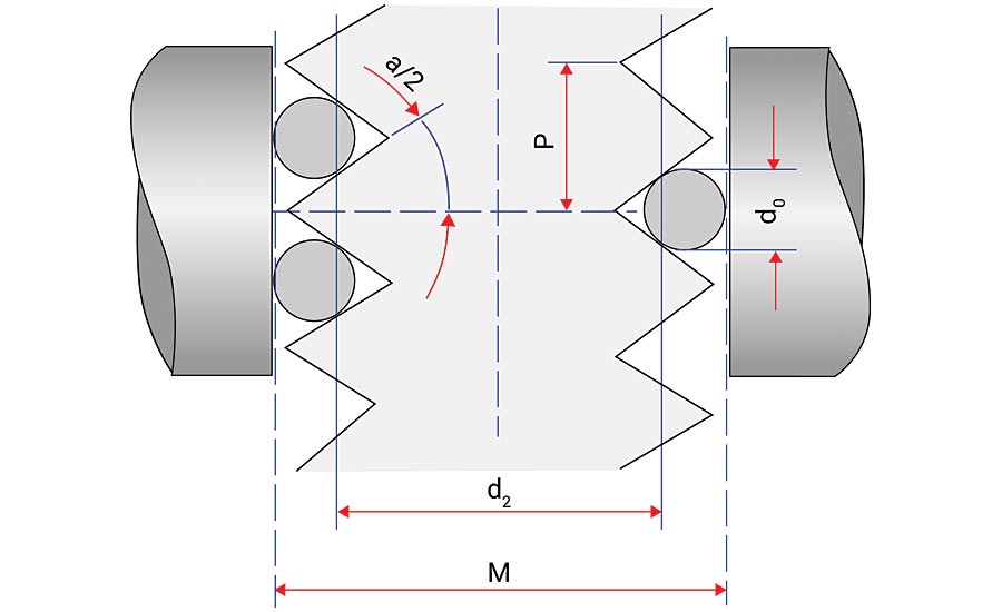
Figure 3: Anatomy of a Thread
Plain Threaded Plugs: Measurement Process
In order to obtain the best possible understanding of the critical dimensions of a master thread plug, it is recommended that a number of measurements be taken at various locations along the thread to ensure that the pitch diameter size is constant and within tolerance over the full length of the plug.
Looking at Tables 2 and 3, a couple of important figures are evident that are sometimes overlooked. The most notable is the gaging pressure, or measuring force, and the fact that the parameter will vary with the size of the gage, as is shown in Table 1. Therefore, the proper gaging force must be within specification prior to performing any thread plug measurement.
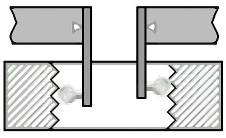
Figure 4: ID jaws with ruby ball tips
The location of the wires can be clearly seen in Figure 3. For most threads, there is not much of an issue making the measurements because the three wires form a triangle and provide for stable fixturing of the threaded plug between the anvils. For plug gages that are small and have very fine threads, there may be a tendency to move the two wires on the one side further apart and skip a few threads to make for a more stable platform. While this may be a good idea, it would not comply with the specification.
To make these measurements a little easier, the thread wires are mounted in a holder that fits over the measuring anvils on the length machine. In order for the measurement to work properly, the thread wires are mounted onto the holders with minimal clearance so that they can float and align to the part and the anvils but remain in place for the measurement process. Errors in the measurement will occur if the wires are stuck and not allowed to locate freely into the pitch of the threads. Additionally, the thread wires, as well as the thread plug and all other items used in the performance of the measurement, should be examined prior to start of the measurement process to look for dirt, nicks, or wear spots. The certification of the thread wires should also be current, as the usage of uncertified thread wires can call into question the final actual pitch diameter.
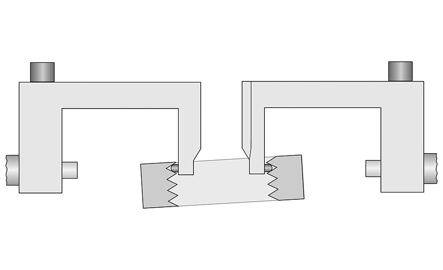
Figure 5: ID jaws with thread ring on angle (not ideal)
Plain Threaded Rings
To review the basics covered in the previous sections, as well as some additional requirements, the following items are needed in order to ensure proper measurement of a master thread plug:
- A set of certified thread wires
- A length measurement system with the required resolution and accuracy
- Proper cleanliness procedures
- A good laboratory environment
However, on the topic of measuring a threaded ring gage, the idea of “basic” measurements are turned inside out. There is no way to properly mount the thread wires used in the three-wire method on the inside of a threaded ring. To accommodate the threaded ring, the measurement must be made with different accessories on the same length machine and, depending on the parameters of the ring, possibly by a length machine with different characteristics and capabilities.
Rather than wires, this application requires inside diameter (ID) measuring jaws with precise ruby ball contacts. The ruby ball contacts simulate the wire diameters and measure the ID of the ring in a similar fashion as one would with a plain ring gage. The difference however is twofold:
First, the ball contacts protrude out further than normal ID jaws to allow the ball contacts to settle within the pitch of the thread ring.
Second, the depth portion of ID jaws are mounted to leaf or pantograph springs that allow them to float in the z-axis. This allows the ruby ball contacts to float freely and find their way into the pitch of the thread.
Both of these factors are illustrated in Figure 4.
Compared to the three-wire method, which has three contact points, the aforementioned special ID jaws only require two contact points to be able to complete a measurement. The three-wire method require three points of contact.
There is also an option for instances where the measuring machine does not have flexible jaws. Fixed jaws can be used with ball contacts but the threaded ring must be tilted at an angle to make the opposing threads parallel to the X-axis of the machine, as shown in Figure 5. This procedure is however not ideal as tilting the threaded ring has the potential to add error to the measurement process.
With the information listed above, it is important to note that rings come in a wide variety of IDs. Using ID jaws is good method for measuring ID threads down to a certain size, with the size of about 1.25” (30mm) being the minimum realistic measurement size for measurements using ID jaws. Measuring smaller ID threads is more challenging and requires a different measurement setup. Instead of having a pair of ID measuring jaws, a single spring-loaded arm with a special lever type, single-axis inductive probe can be used with a T-style contact having two ruby ball contacts. Between the LVDT sensing the deflection of the ball contact, the spring allowing for a small z-axis movement for alignment purposes, and the scale of the length machine measuring the position of the gage head, a calculation can be performed with only two touches of the threaded ring, as shown in Figure 6.
It is important to note that the above processes only apply to measuring a solid threaded ring. This is because any software-driven precision length measurement machine will assume that the ID of the threaded ring is perfectly round, which cannot be guaranteed in the case of an adjustable thread ring. The measurement process for certifying an adjustable thread ring requires a corresponding certified master thread plug.
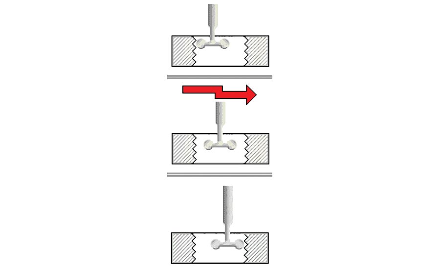
Figure 6: Measuring thread rings using an inductive probe
Tapered Thread Measurement
Just as the plain cylinder is the basis for the threaded plug gage and the plain ring gage is the basis for the thread plug, a similar comparison exists for the tapered thread masters. In this case, a taper plug gage is the reference for the taper threaded plug and a taper ring master is the reference for the threaded taper ring.
The critical factors when certifying tapered test pieces are (1) certifying the height of the z-axis prior to measurement and (2) measuring two diameters at two different, known heights. These two factors allow the angle of the tapered test piece to be determined. This is true for plain taper test pieces as well as tapered thread masters. Certifying the z-axis height and then measuring the two different heights requires a different level of precision length measuring machine, one with not only a highly accurate x-axis scale but also a similar level of precision in the z-axis scale. Having a part-staging assembly, a “table” of sorts, with the ability to tilt precisely to that angle of the taper ratio, is also required.
For the measurement process, each tapered thread master ring requires four readings to be taken, two readings each at two different diameters on as shown in Figure 7. As with plain threaded rings, this measurement process only applies to solid tapered thread rings.
The process for measuring tapered thread plugs is similar and is shown in Figure 8.
Tips for Millionth Measurements
There are a lot of steps and accessories required with a precision length machine—and the more complex the gage steps in the measurement are, the better chance that there is going to be some error in the measurement. Therefore, each step in the measurement process of master threads must be performed with the absolute care. Sub-micron gaging must be performed in a controlled environment: a special room that is free of vibration and thermally insulated from the shop floor, where temperature is kept within 68±1°F as possible and the temperature gradient does not exceed 0.9°F/hr. When a part comes in from the shop, it should be allowed to sit untouched in the laboratory environment for several hours on a heat sink (eg. a large steel plate) to bring its internal temperature into a state of equilibrium with the master and the precision length measurement gage before the measurement process begins. Even with all of these precautions, the gage should be mastered frequently to ensure the highest level of measurement accuracy.
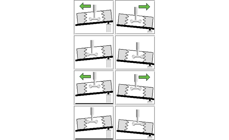
Figure 7: ID tapered thread ring measurement process, showing the angle adjustment
Elaborate measures are also required to combat the problem of contamination. Relative humidity in the room should be kept below 50% to inhibit the formation of rust and above 35% to inhibit the build-up of static electricity, which have the potential to harm the sensitive electronic components of the gage. Parts must be thoroughly cleaned of dirt and even thin oil films prior to gaging. The choice of cleaning solvent will vary with the application and may require some trial and error to ensure that the solvent itself doesn’t leave a film.
It is necessary to regularly clean the entire gaging area, including the gage and masters, to remove dust, skin oils, etc. This is especially true of thread masters with very fine threads, as dirt and oil can easily become caught in the pitch of the thread. Normally, wiping the surface of the threaded masters with a cloth dampened with alcohol is not enough as this does not necessarily get down to the very root of the thread to completely clear out even the smallest contaminants. One option to thoroughly clean a test piece is to place the threaded master in an ultrasonic cleaning tank to loosen any dirt or oil in the threads and then use a fine brush to clean out the threads.
Even with sophisticated gages that are fully capable of the task, measuring to submicrons remains a challenge. It requires thorough planning, careful selection of conscientious and well-trained personnel, and significant investments in training programs and facilities, as well as a good understanding of all the variables that can affect the accuracy of submicron dimensional measurements.
Figure 8: OD tapered thread plug measurement process, showing the angle adjustment
Specific Tips for Thread Measurements
It is clear that a precision length machine is the tool of choice for high-accuracy thread measurements. This is because the application requires a long measuring range to handle a variety of thread sizes and potentially the need for a precise z-axis.
There are methods to reduce the error found in the measurement process. One method is to reduce the size range between the certified master gage and the part being certified on the length measurement machine, also called the “test piece.” While a precision length measurement machine can have a long measuring range, an extended range between the master and the test piece can add error to the measurement result. To reduce some of this error, use a certified master to set a nominal size close to the measuring diameter of the test piece. For example, if the test piece is a 2” (50mm) diameter threaded plug, one could first master the distance between the contact tips (without thread wires attached) using a 2” (50mm) plain master plug and then proceed to measure the threaded plug test piece using the three-wire check. The close proximity of the diameter of the plain master plug to the diameter of the threaded plug test piece removes the errors associated a potential long range between the master and the test pieces. The longer the range between the sizes of the master gage and the test piece, the greater the potential for length errors in the machine.
Master thread gages are also available in different tolerance classes similar to how AGD rings and discs are classified, specifically W-, Y-, and X-class. To measure an X-class thread master, be prepared to obtain the most accurate equipment and create the best laboratory environment for that equipment. Otherwise, measurement uncertainties due to the equipment and the environment will be a large portion of the tolerance budget.
Charts and tables in various publications show the theoretically perfect constant for each thread pitch along with the corresponding ideal thread wire size. Many people make the mistake of using values from those sources. In actuality, the correct constant is based on a calculation using the certified diameter of the thread wires which is why performing the three-wire measurement requires certified thread wire sets to ensure maximum accuracy.
Looking for a reprint of this article?
From high-res PDFs to custom plaques, order your copy today!


