The Importance of Grip Selection in Force Measurement
Putting these rules to work will dramatically improve sample alignment and measurement reliability.
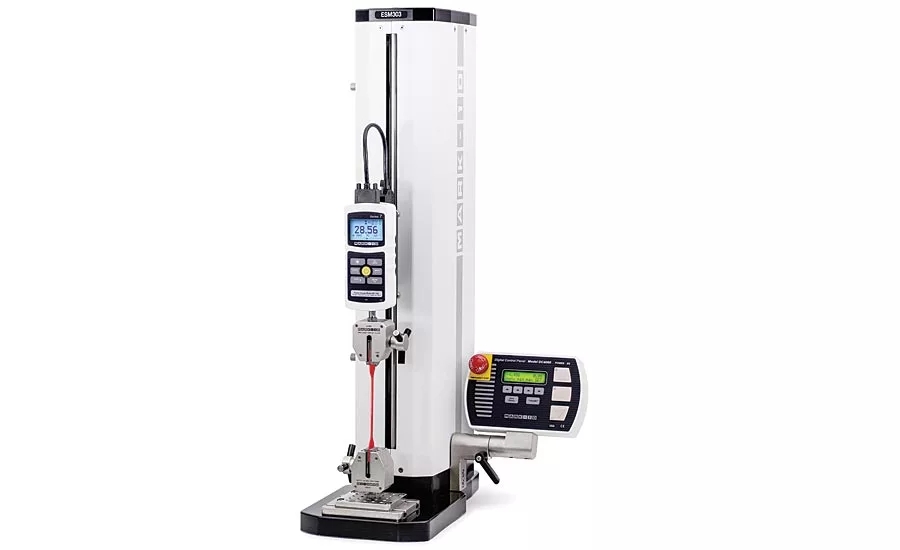
A force measurement testing machine is shown with a pair of wedge-action grips. The machine’s preload function zeroes out the force offset produced by the “first bite” of the spring-loaded grip jaws. Source: Mark-10
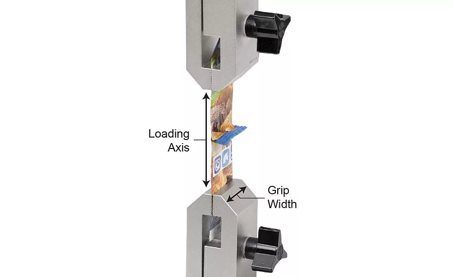
A grip’s width should be as closely matched to the sample width as possible. Source: Mark-10
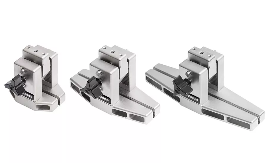
Certain grips are available in several widths to accommodate a range of sample widths. Source: Mark-10
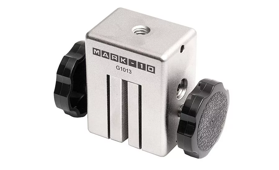
A parallel jaw grip is an effective alternative to wedge-action grips in certain applications. Source: Mark-10
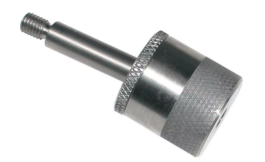
Swivel joints mitigate the effects of slight non-axial loading. Source: Mark-10
Force measurement, defined as the measurement of tensile or compressive loads acting upon an object, is an indispensable method of assessing and ensuring the quality of materials, components, and assemblies. Force measurement equipment typically orients a sample axially, to ensure consistency and accuracy. However, a number of further considerations should be made to ensure as accurate a measurement as possible.
Surprisingly, the accuracy of the instrument itself—though important—is only one piece of the measurement accuracy puzzle. Many factors contribute to the final accuracy, including proper sample alignment, testing machine crosshead speed, data sampling rate, and others—but one of the most critical factors is grip selection.
A wide range of grips are available to accommodate different sample dimensions. Although many grips are designed specifically for a particular application, sample alignment is not guaranteed. Sample alignment’s role in ensuring accuracy is regularly underestimated. Although it is conventionally supposed that force interactions of a uniaxial test are confined to a single linear dimension, these forces actually exist in three dimensions, affording exponentially greater opportunity for misalignment and non-repeatability.
Assuming a force measuring instrument was properly calibrated, it is fair to further assume that its response curve was established by a series of loads with near-perfect alignment. If the instrument’s sensor is then subjected to misaligned loads during testing, the entire basis for measurement traceability is no longer applicable. For valid measurement traceability, the alignment of the measured force, with respect to the sensor, must be the same during testing as it was during calibration.
Proper load alignment during force testing is almost entirely contingent on the grips and fixtures used to articulate the sample. And, when it comes to grips and fixtures, determining which configuration is best suited for a given application requires much more than just deciding if they are large enough or strong enough.
The good news is that there are some simple, general rules that underpin the art of grip selection. Putting these rules to work will dramatically improve sample alignment and measurement reliability. Below are a few of the easiest and most effective tips.
Select the smallest applicable grip width
Grip width refers to the length of the non-opening dimension of the grip, which runs perpendicular to the loading axis. Grip width describes the widest sample size that a grip can accommodate.
Often, there will be a basic grip design that is available in several different grip widths. The most common example is grips for peel testing. Since peel strength results are calculated in terms of force per unit width (such as lbF/in or N/cm), films, seals and adhesives need to be tested in a variety of specified widths. Therefore, it is common for a particular peel testing grip design to be available in several widths.
In cases like this, it is best to choose the smallest grip width that will still accommodate the sample. If several sample widths require testing, it is advised to use several grips, instead of one larger grip to accommodate all sample widths.
While the widthwise edges of the grip should always extend beyond the sample edge, having a grip width that is only slightly larger than its sample improves the operator’s ability to visually inspect sample alignment. If the edges of a sample run immediately adjacent of those of the grip, it will make sample misalignment more obvious.
Adding a swivel joint for tensile measurements
The simple swivel joint accessory has one of the largest performance to price ratios in all of force testing—and is also one of the most underutilized.
If a sample exhibits asymmetric elongation when subjected to a tensile force, it will apply an eccentric and/or torsional load to the force sensor when tested. Eccentric and torsional loads can induce extreme measurement errors—and even cause damage—to many force sensors.
Inserting a swivel joint into the load chain does not directly address the cause of the off-axis loading but can mitigate some of its negative impacts. This is achieved by better centering the force vector and preventing a force sensor from being rigidly coupled to a bending or twisting load.
An added benefit of a swivel joint is it can make misalignment issues immediately obvious. With a swivel joint, a sample is able to swing freely in space and will hang off to one side when asymmetrically loaded. This will allow the operator to more frequently identify and correct such issues. Without a swivel joint in the load chain, the force sensor will be rigidly coupled to the sample, potentially hiding a misalignment issue.
Caution: Automatic preloading from wedge-action grips
Wedge-action grips are valued for their unique ability to tighten automatically as the sample thins during tensile testing, thereby preventing slippage. This self-tightening feature is initiated by an internal spring mechanism that constantly applies a small pinch load to the sample. This mechanism enhances ease-of-use while creating a more repeatable “first bite” from the jaws.
But, a complication of this wedge action is that the jaws simultaneously move along the loading axis as they pinch inward. So, this initial pinch inward is accompanied by a compressive load applied to each sample.
Often, an operator will make a habit of zeroing the force display immediately after the sample is secured within the grips. This can be problematic with wedge grips because of the compressive loads they naturally generate. Zeroing the force channel with this preload applied will cause subsequent tensile force measurements to contain an artificial offset, inflating measurement results.
An effective solution, which is particularly effective when working with more rigid samples, is to instead choose parallel jaw grips. As the name suggests, parallel jaw grips have jaws that run parallel to the loading axis, so their inward pinch acts entirely perpendicular to the loading axis. Thus, unlike wedge grips, parallel jaw grips can apply a pinch load without necessarily creating a preload.
Caution: Sample squirt from parallel jaw grips
Although parallel jaw grips do not generate a compressive preload through their direct action, they do still sometimes exhibit a different preloading issue: “sample squirt.” As their strong inward pinch load is applied to more elastic samples, the sample will often be squeezed outward from the jaws. The effectively longer length of sample that is now situated within the original grip spacing will result in a compressive preload and/or added slack in the load chain.
The Resolution
To solve the issues of preloading from wedge grips and sample squirt from parallel jaw grips, the best option is typically to utilize a test system with a preload feature. This feature can instruct the crosshead of the test machine to travel to a configurable load before establishing the test datum. In the case of wedge grips, this will relax the compressive preload before establishing a force/displacement zero. In the case of parallel jaw grips, this will remove the added sample slack before establishing a force/displacement zero.
In both cases, utilizing a preload will create a known and reproducible set of initial test conditions that will greatly improve measurement accuracy and repeatability for both the force and displacement dimensions. In applications where accuracy and repeatability are critical, the preload feature can be indispensable.
Selecting grips and fixtures can seem like as much of an art as it is a science, but with these simple tips, it is possible to avoid fixturing errors and ultimately achieve more reliable force measurement results.
Looking for a reprint of this article?
From high-res PDFs to custom plaques, order your copy today!


