Cutting Edge Hardness Testing
Accurate testing for hardness is vital to ensure a high quality product.
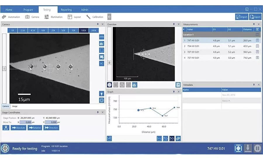
Figure 1: Microhardness indent performed on Knife Blade Tip, HV10gf 747 @ 26µm from blade tip. Tester: VH3300 automatic hardness tester with DiaMet software.
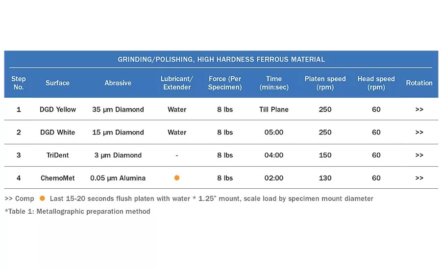
>> Comp --Last 15-20 seconds flush platen with water * 1.25” mount, scale load by specimen mount diameter
*Table 1: Metallographic preparation method
Inspection of manufactured goods has increasingly become standard practice to ensure products meet more and more demanding specifications. In some cases, this can mean that long established methods of quality control need to be pushed to their limits. One example is the heat treatment of steel. Hardness testing has been used to check heat treatments for more than 100 years. As applications have become more specific, and technical developments more refined, the test methods have developed further alongside technology. In the highly competitive cutting blades industry, it is vital for the blade to have sufficient hardness to retain an edge, while too hard can cause brittle failure.
When hardened materials are ground, residual heat may alter the microstructure and soften the blade edge. By design, the blades have little mass, so control of residual heat during the final finishing process is also critical. Accurate testing for hardness is therefore vital to ensure a high quality product. Testing the hardness of the cutting blades becomes challenging as indents must be made and measured accurately, using low loads and correspondingly small indents. This requires proper specimen preparation and careful use of hardness testing equipment. This article will review a guide to metallographic preparation and microhardness test processes for this application, although the principles are relevant to the use of Vickers testing for any hard material applications.
Challenges
Before diving in to specimen preparation, it is important to select methods appropriate to the specimen material and expected hardness. For our blade example, the expected Vickers Hardness (HV) value may be upward of 700HV and can easily extend into 1200HV range. For such a hardened part, the inspection sample will need to be mounted, ground and polished while maintaining a flat edge. Flatness is of paramount importance for obtaining valid symmetrical hardness indentations, as tilt or rounding in the specimen can cause significant errors in measurement.
The ASTM-E-384 Standard for Knoop and Vickers hardness testing recommends that any indent shall be 2.5X its diagonal size away from any edge or other indent. Placing an indent close to the blade tip therefore requires low loads, such that the expected indent diagonals will be very small, i.e. 4 to 5 µm diagonal length. With such a small indent size, accurate measurement would be very difficult if the hardness tester does not have high magnification objectives. Even with a 100X objective, measuring such small indents manually with an eye-piece can vary significantly between operators. These factors affect repeatability and reproducibility of hardness test results.
Metallographic Preparation
With detailed focus on specimen preparation, one can significantly reduce the amount of time for getting the specimen ready for hardness testing. Using a high precision sectioning saw can allow sectioning very close to the area of interest without the risk of specimen damage or heating. Cubic Boron Nitride blades are more suited to ferrous materials than diamond, although abrasive blades can also be used on some machines. The cut should be at a distance away from hardness test plane and that takes into account the expected thickness for grind and polish removal and the thickness of the sectioning blade. Generally, with less damage created during sectioning, less grinding will be required (with coarser grits); in turn, this reduces the risk of damaging the area of interest.
With cutting blades or other specimen materials having high aspect ratio, it is preferable to mount several blade samples together. Not only can this be more efficient, but having multiple specimens will keep the mount more stable during preparation and help retain flatness. Using support clips is a convenient way to hold the samples perpendicular to the mount bottom plane.
The mounting material should be selected with characteristics of maintaining best edge retention: high hardness and low shrinkage. Two types of mounting routes are available to choose: hot compression or castable mounting. With a compression mounting process, the best choice would be a fine grain, hard, mineral filled, epoxy material, such as Epomet F. With castable mounting, the best selection would be a hard, very low shrinkage acrylic material, such as VariDur 3003.
It is important to clean and dry the samples well before mounting; not doing so can result in shrinkage gaps between the specimen and mounting material. Shrinkage gaps prevent the edges of the specimen being supported during preparation, which results in edge rounding, and are also sites that collect and disperse contaminants during the grinding and polishing process.
The use of a semi-automatic grinder/polisher allows more reproducible and consistent preparation. To get the specimens as flat as possible, diamond grinding discs (DGD) and no-nap cloths are recommended. Central force grinding was also used to ensure uniform grinding and maximize planarity. With preparation of very hard material, it is important to minimize the amount of time polishing on soft surfaces, as this can also cause edge rounding, so polishing steps should be optimized and not be excessive. If the finish is not good enough after the last stage, rather than polish longer go back and repeat earlier stages. The polishing route used is outlined in Table 1. A series of Apex DGD grinding discs were used to planarize the sample, and sequentially reduce scratches. Diamond discs are far superior to silicon carbide paper for retaining flatness. The TriDent cloth used for 3 µm diamond and the ChemoMet used for the 0.05 µm final polishing step were both selected for attaining best flatness in the sample.
Microhardness Testing
Selecting the proper setup for microhardness testing on cutting blade specimens is critical. Proper system configuration is also important. For low load microhardness testing, the tester should be isolated from environmental vibration. If vibration is an issue, inaccurate load application can occur. Given that the test area is limited to the blade tip, repeating an indentation may require re-preparing the specimen. Therefore, an indent to be placed at the blade tip leaves no room for error. The hardness tester needs to be accurate and repeatable at low loads. A load cell tester allows highly accurate application of load, whereas drop-weight testers can be prone to slight overloads. Regardless of which type of tester is selected, the tester must be accurate, repeatable and in compliance.
When measuring low load indents, a 100X objective is a must. ASTM E384 addresses the inherent difficulties with making and measuring indents below 20 µm due to the various possible measurement errors. A 10% error (0.4 µm) in measuring 4 µm size indent at 100X through an eye-piece may not be uncommon, as the limits of optical resolution are being reached. Measurements made on a monitor improve accuracy and are highly repeatable than those measurements taken through a filar eye-piece, due to improved visibility. When diagonals are down to 4 µm size, a digital image makes measuring such small indent easier. The option of digital magnification would further improve measurement repeatability and accuracy.
Today’s automatic hardness system use computers and integrated software to control the hardness tester. It becomes an intelligent tester using sophisticated measurement algorithms to capture an indent’s image and measure its diagonal lengths automatically. Auto-measurement allows fast, accurate and repeatable results and will convert the measured diagonals directly to a hardness value without requiring an operator to perform any calculation or use a look-up table. All of these functions help to significantly reduce the error and variance between operators.
The tester needs to be capable of locating and placing indents at designated points. An automatic tester will allow programming of hardness traverses with multiple indents at designated locations. The more intelligent software system allows specimen tracing and indent placements over created templates. For high volume quality verification testing, multi-sample testing can significantly reduce testing operation time. Time studies on automated hardness testing have shown a time-saving of over 80% compared to manual testers. Of course, the test process will vary for each situation, but actual time-savings are generally significant.
Summary
Quality assessment of cutting blades has its challenges, but these can be overcome. Technique and attention to details with specimen preparation is a key factor to success. Having the specimen flat with no edge rounding will allow an indent to be placed near the blade tip. The use of semi or fully automatic grinder/polishers will provide uniform, reproducible specimens.
The use of automatic hardness testers with integrated software systems and high quality optics is the other key factor. They reduce operator error and variance between different operators. Auto-measurement of indents is quick and accurate; indent placement is precise and repeatable, and the total hardness test time is significantly reduced.
Looking for a reprint of this article?
From high-res PDFs to custom plaques, order your copy today!


