Reverse Engineering: What’s it all about?
There are several scenarios in which reverse engineering is important for modern manufacturers.
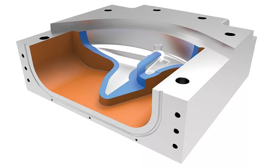
One half of the finished layup tooling.
Point cloud converted to a mesh of nearly one million triangles.
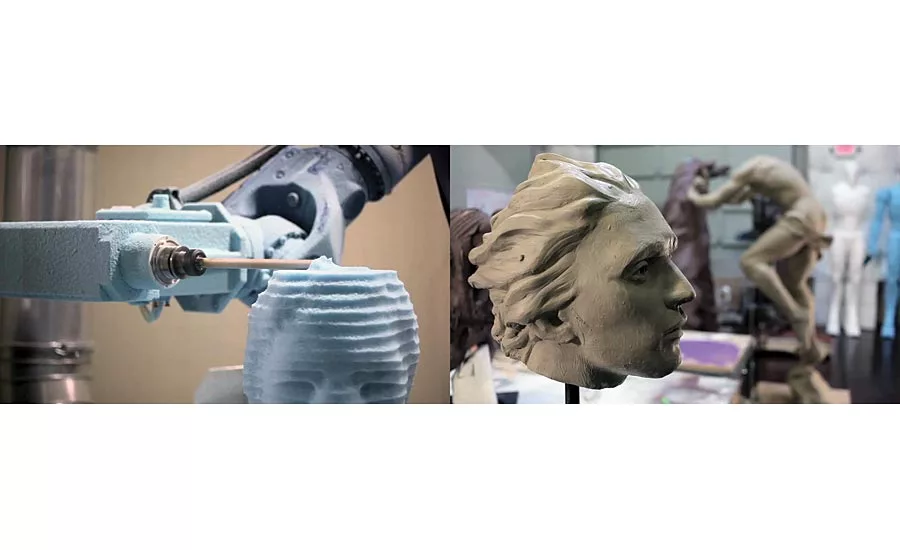
Additive Workshop machine foam casting models directly using a 7 axis robot.
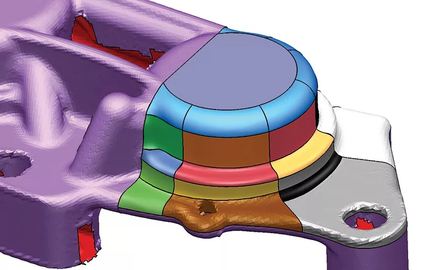
Partial shrink-wrap of a simple part.
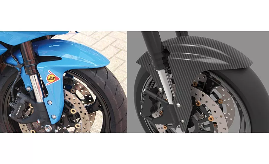
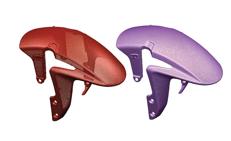
Original mudguard for a Honda CBR 600, and proposed carbon fiber after-market replacement.
The term reverse engineering can be applied to a wide range of technologies, including disassembling computer code, genetic modification, and many more. For engineering applications, it is more usually thought of as the conversion of physical parts into digital models.
There are several scenarios in which reverse engineering is important for modern manufacturers.
Repairing damaged components
Many machines and tools are still in operation that were designed and made before CADCAM came into common use. If any parts of these machines become damaged they must be repaired or replaced as quickly as possible, to avoid costly downtime and loss of production. If the part is simple, this is not too difficult, and often it is possible to measure the geometry adequately using nothing more than a set of Vernier calipers. If the part is complex, for example the doubly-curved faces of a press die, reproducing it accurately is considerably more complex and time-consuming.
Sometimes it is simply a case of needing some form of updated record of a part for which no CAD exists. Again, this is straightforward for geometrically simple parts, but considerably less so if the part is complex.
Producing after-market spares or replacements
After-market automotive parts give customers a wider choice of replacement parts. They also offer the customer significant savings, typically costing much less than the ‘official’ equivalent. Typical examples include body panels and trim parts, for which tooling must usually also be made. Although this represents a significant investment for manufacturers, the rewards can be substantial, with the market being estimated at over $3 billion a year in the U.S. alone. This value is likely to increase further as manufacturers look to the possibility of creating specialist engineered-to-fit parts in more exotic materials such as carbon fiber.
The typical reverse engineering process
Reverse engineering begins with the acquisition of the part geometry itself, usually using some form of scanner. The choice of scanning technology depends heavily on the type of part being scanned. Parts with lots of surface texture and color are best scanned using photogrammetry techniques, while those with complex 3D forms are often better suited to scanning with laser. Most modern scanners can capture in excess of half a million points per second, producing a ‘cloud’ of 3D points, which is then converted into a mesh of triangles.
The next step will be dictated by the intended end use of the model.
Copying to scale
If the final part is simply to be a direct copy, then in many instances all that is necessary is to clean up the mesh. Optical scanners cannot always ‘see’ all regions of the part, so any missing regions must be filled, either with simple planar caps, or smooth curved patches. Scanning can occasionally introduce noise, or capture unwanted data, so it may also be necessary to refine and filter the mesh to remove any points that are outside a chosen tolerance. This method of reverse engineering is often used to create large scenery pieces for theme parks and movie sets. A hand-made maquette is converted into a 3D computer model that can then be scaled to finished size. Manufacturing such large pieces used to be a major challenge, requiring the creation of 2D templates that allowed the sculptors to match key sections from the original maquette to the final model. Nowadays, large scale parts such as these are often machined directly into foam, or even stone, using multi-axis NC machines, or industrial robots.
Converting meshes to surfaces
For engineering applications, it is more usual to need to convert the scan data into surfaces or solids, or a combination of both, known as a hybrid. Although CAD systems exist that can cope equally well with surfaces and solids, only a handful can deal with 3D mesh data directly, particularly if the component is to be made by some kind of molding process, requiring the part to be split into cavity/core and run-off surfaces.
There are two main approaches to this process, each with its own advantages and disadvantages. As before, which is most suitable for any given application will depend upon the intended use of the final part. Another important consideration is the manufacturing method, if any, to be used in the final production.
Shrink-wrap surfaces, the ideal choice for reverse engineering?
Shrink-wrapping cloaks a shape in a patchwork of close-fitting surface patches. The advantage of this method is that the process is largely automatic, often requiring little or no user intervention, apart from specifying the patch density. If the end use of the model is to acquire a CAD record of a part from which no CAD exists, or to recreate the part using 3D printing, or similar process, the speed and simplicity of shrink-wrapping make it an obvious candidate.
The disadvantage is that it is virtually impossible to edit the model in any meaningful way. For example, offsetting a planar region to provide machining allowance for cast parts may require several dozen surfaces to be modified—not just the face itself. Offsetting the initial face is quite a simple task. Ensuring all neighboring faces are updated whilst also maintaining tangency, is considerably more challenging and likely to require a lot more time and effort. If the surrounding regions are especially complex, this kind of change becomes very difficult indeed. Add complex free-flowing fillets, and it becomes almost impossible.
Another disadvantage of shrink-wrapping is that it generally requires a completely closed and watertight mesh, as otherwise the surfaces may become badly distorted in undefined regions, as they attempt to match up with surrounding faces. If the part surface is hard to scan, for example if it is very shiny, then the amount of time taken to fully repair the mesh may outweigh the speed gains.
Exact copy or design intent?
In many cases the desired result is not merely a copy of an existing part. If the part is old, damaged or worn, as is often the case, copying it will only reproduce any defects. What is needed instead is to re-define the part using up-to-date modelling techniques, using the mesh as a basis for making sensible decisions as to appropriate dimensions, with the aim of getting as close as possible to the original design intent.
Most reverse engineering software offers a variety of tools to achieve this end. One common technique is for the software to identify regions that can be represented by primitive shapes such as planes, cylinders, cones etc. Merging these shapes together using standard solid or surface modeling tools gives the basic part. Finishing touches such as holes, fillets and chamfers can be added quickly and easily using traditional solid modelling techniques, to finalize the design, with the mesh acting as a guide to the sizes.
Although this approach works very well for parts that are largely prismatic, it is less effective if the part is doubly-curved and complex. For this type of geometry, shapes are usually created from curves generated by taking sections through the mesh. This tends to give curves that are composed of lots of segments of line. Converting these profiles into surfaces will naturally result in faceted forms that are unlikely to meet the original intention of the design.
The general rule when creating smooth shapes is to use the fewest defining points, so section curves are typically approximated using arcs and lines. If the result is not sufficiently accurate, most systems also provide tools to reduce the point density while maintaining accuracy to a known tolerance. This not only reduces the number of points, but also allows the user to edit the arcs and lines to adjust the values, usually simply by rounding up or down to achieve sensible numbers.
As when using segmentation tools, fillets, holes, chamfers and other features can be added quickly and simply. The end result is a fully detailed solid or surface model that can be modified conveniently if necessary.
Preparing molds and dies for mass production
If the part is to be molded, it must first be scaled to compensate for shrinkage, modified to ensure that there is adequate taper, and finally divided into separate mold pieces, complete with split surfaces. These types of operation fall outside the scope of pure reverse engineering though, so it is usual for the finished design to be passed to a separate CAD system.
This workflow means that organizations typically need two entirely separate systems, one for reverse engineering and another for preparing parts for manufacture. A much more convenient approach is to have reverse engineering tools available directly inside a CAD system that already has powerful and proven modelling for manufacture tools. This enables the entire workflow, from initial scan to final production ready tooling to be carried out in a single program, minimizing learning times, reducing costs, and speeding time to market.
Looking for a reprint of this article?
From high-res PDFs to custom plaques, order your copy today!


