Perfecting Your Manufacturing Eddy Current Test
How to specify a proper eddy current test and develop a prototype to validate your test assumptions.
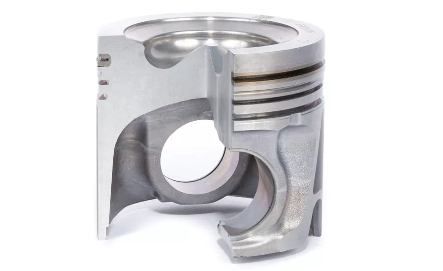
Figure 1. Cutaway view of a piston. Source: Criterion NDT
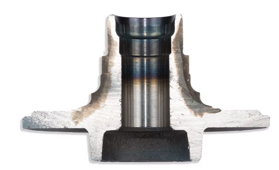
Figure 2. Cutaway view of an automotive wheel bearing showing hardness patterns. Source: Criterion NDT
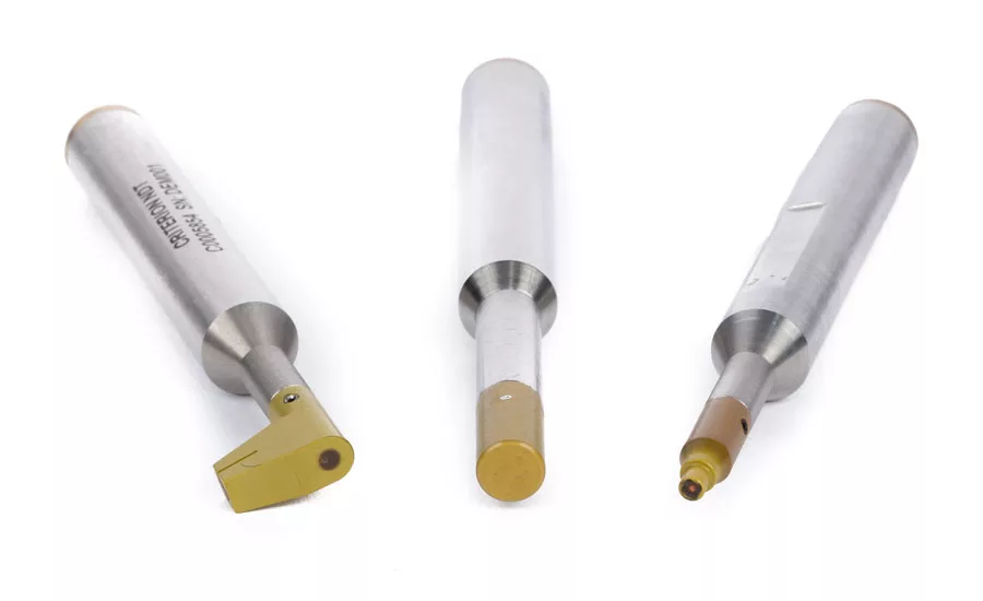
Figure 3. Standard eddy current pencil probes used for crack and flaw detection.Source: Criterion NDT
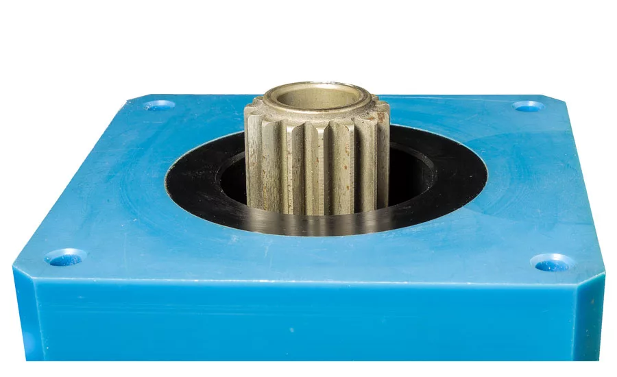
Figure 4. Standard eddy current encircling probe with gear. Source: Criterion NDT

Figure 5. 3D printer making prototype custom eddy current probe body. Source: Criterion NDT

Figure 6. Winding prototype custom eddy current coil. Source: Criterion NDT
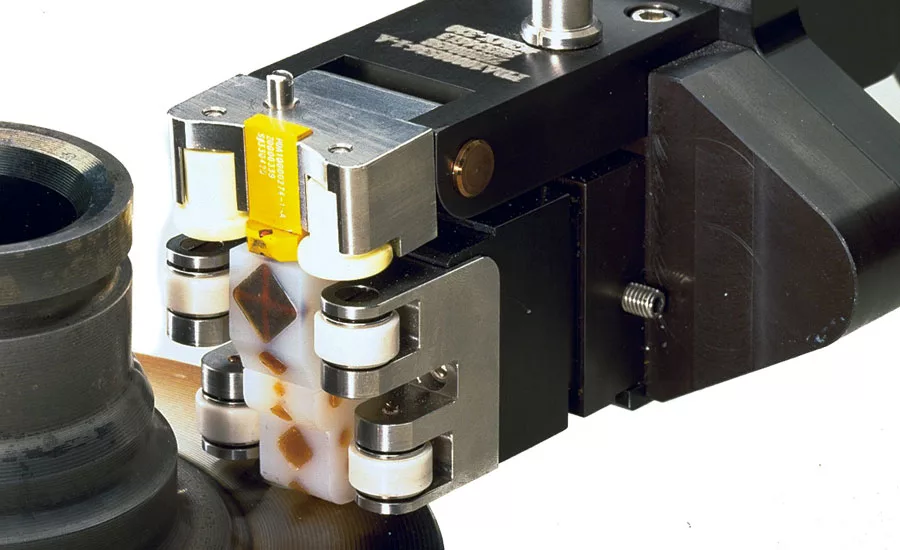
Figure 7. Production eddy current probe for wheel bearings with eight coil windings and ceramic wheels. Source: Criterion NDT
We test our products to ensure that they ship without defects. This helps reduce our scrap and warranty costs, and above all, create and deliver products that meet our customers’ needs.
Our testing designs must anticipate the actual failure mechanisms that occur in the field. We must also focus our testing on critical areas where a failure will be most costly. A small flaw or heat treat discrepancy in one area of a component may have no effect on the function, fit and finish of that part. Yet, if that same condition were to occur in a critical area, such as a bearing race, the part may fail prematurely.
In this article, we’ll look at how to specify a proper eddy current test, and how to develop a prototype to validate our test assumptions. We’ll also look at how to implement that test in a production environment integrated with material handling systems, for 24/7 operations and minimal staff supervision.
Specifying the Test
While we are tempted to say “let’s test the whole part with eddy current,” real world testing doesn’t work that way. Often, “testing the whole part” is either not possible or unnecessary. As with other nondestructive testing techniques, you must first specify what you are trying to test for, where you want to test, and then define the pass/fail criteria. Eddy current testing can be used to find cracks and flaws in metal components, determine whether heat treatment was performed and/or done correctly, and find mechanical manufacturing anomalies, such as improper threading or spline installation. The criteria for each of these tests are different.
For detection of crack and flaws, it’s important to establish the location of interest and the minimal detectable flaw size that you want to find. Figure 1 shows a cutaway of a piston. For this test, the component manufacturer wanted to look at specific, critical areas in the combustion bowl. The manufacturer specified these locations on a drawing of this component.
Minimum flaw size can be a subjective call. With a flaw detection requirement that is unnecessarily aggressive, the manufacturing line will likely get a significant number of false rejects. Once the minimum flaw size is specified, sample reject (red rabbit) parts are machined using conventional or EDM techniques, depending on the flaw requirement.
For heat treat validation, it’s also critical to establish minimal acceptance criteria. For a simple part, like a ball or roller bearing, it can be a specific Rockwell standard that must be met. For a complex part, like the cutaway wheel bearing shown in Figure 2, a complex test coil design using multiple sensors that are carefully located is required to check for proper heat treat and case depth patterns.
For detection of improper thread conditions, it’s important to create criteria that best meet anticipated process conditions. These are usually no-thread, short-thread, double-tapped or even broken-tap scenarios. Samples of these conditions can be readily created.
Developing a Prototype Test
Developing a prototype eddy current probe and testing it out on samples of production parts helps to ensure that the eddy current application is feasible and will operate correctly in a production environment. The eddy current instrument supplier will work with the component manufacturer to establish the correct implementation of the technology. This cooperation ensures that the areas in need of testing are addressed, and that the minimum detection requirements can be achieved. The component manufacturer needs to provide the eddy current supplier with engineering drawings and product samples reflecting both good and failure conditions.
The eddy current testing supplier will then evaluate whether standard eddy current pencil probes (Figure 3) or standard eddy current encircling probes (Figure 4) can be used for proper evaluation. If not, eddy current probe bodies can now be quickly built using a 3D printer (Figure 5). Prototype coil impedances are calculated and coils are custom wound specifically for the test (Figure 6).
Once produced, the prototype eddy current probe is connected to an eddy current instrument and set up to test the sample parts. After proper go/no-go criteria are verified, a test report is generated and reviewed prior to creating production eddy current probes.
Production Testing Equipment
Production eddy current system design must consider a number of production factors. These include manufacturing throughput (parts per hour), material handling requirements, and the skill level of the production line managers.
Production probe designs are usually “beefier” than the prototype probes. The probe fixturing is often made using a combination of materials such as aluminum, stainless steel and nylon. The fit and function of the probes are of primary importance while ensuring that they easily integrate with the production line material handling solutions. Durable materials such as ceramics are often used in high-wear areas, and are designed to protect the eddy current coil windings. Cabling must also be robust to handle a normal production environment, using high-flex rated wiring and abrasion resistant jacketing.
An example of a production fixture probe can be seen in Figure 7. This probe is designed to simultaneously test eight areas on an automotive wheel bearing component.
Production-ready eddy current systems must have the ability to interface directly with industrial automation systems, or alternatively, via PLCs. The eddy current instrument I/O must be able to communicate with the industrial automation system for part loading, when the test is taking place, and when the test is over. It must also communicate where the component has tested positive to send it to the next production station, or send it to a reject chute if the component fails the test.
The material handling system for the probe shown in Figure 7 locates the bearing into near proximity with the eddy current probe. It must then move the probe to engage with the bearing. The system then spins the bearing to ensure full coverage of the circumference. I/O signals to the eddy current instrument initiate and then disable the test. Once complete, the system sends a command to retract the probe and sends the part onto the rest of the line, or moves it to a reject area, depending on the outcome of the test.
Eddy current instruments must be easy to set up and operate once put into place. Many of these systems may run three shifts per day for months on end. Touch screen displays that offer an intuitive user interface are becoming more popular and provide a great benefit to users.
Conclusion
Designing an eddy current test takes careful thought and planning from understanding the test criteria, prototyping the actual test, and the building of equipment suitable for a production environment. Taking these steps will help to perfect your eddy current inspection process.
Looking for a reprint of this article?
From high-res PDFs to custom plaques, order your copy today!


