Demystifying Eddy Current Heat Treat Verification
It is a fast, repeatable test that integrates well into factory production lines.
Voodoo magic, smoke and mirrors: For some, these are words that come to mind when the subject of eddy current testing for heat treat verification is mentioned. Often, quality and production personnel may have some knowledge of using eddy current for defect detection. But eddy current for heat treatment process verification is a different story. Yet, with a little review of electromagnetics, a complex concept can be made simpler to understand.
Basic Electromagnetics
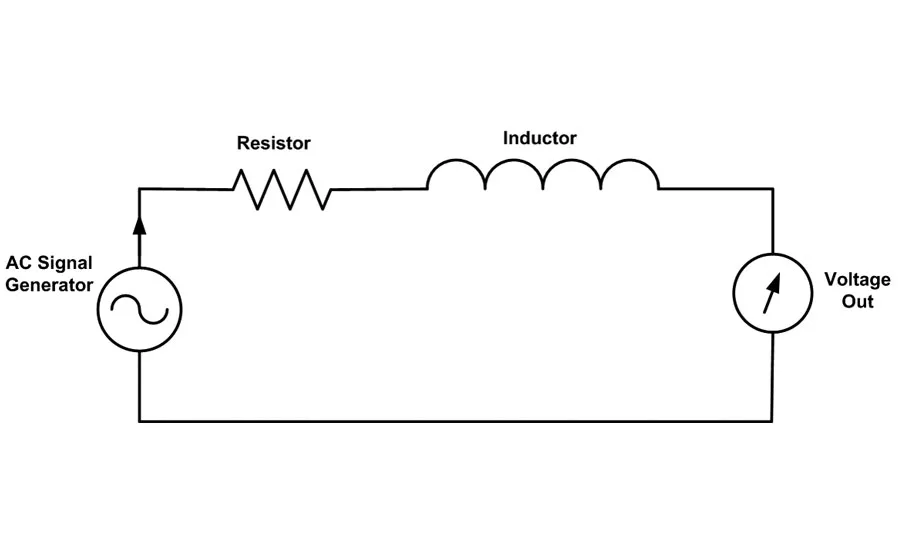
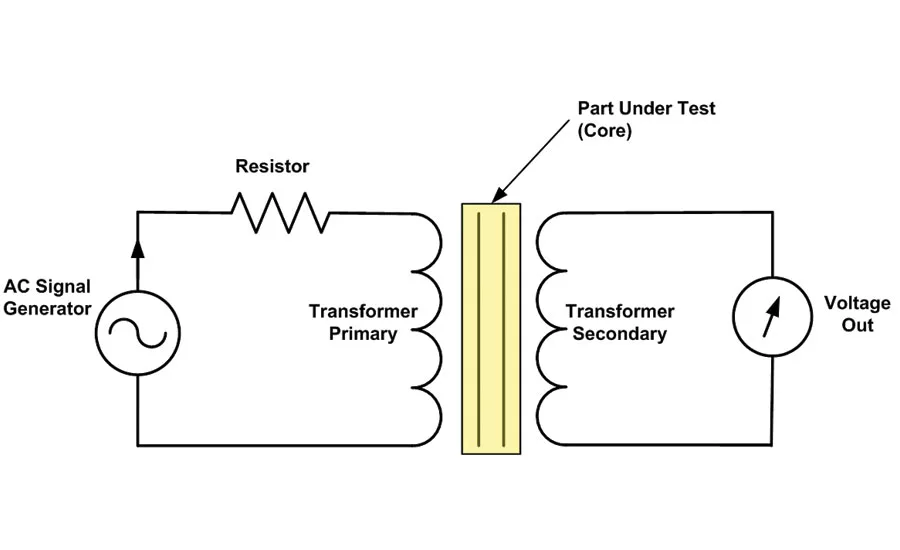
Figure 1 shows a basic inductive circuit. An AC signal generator drives a current through a resistor and an inductor. The “load” across the resistor is called resistance (R), and the “load” across the inductor is called inductive reactance (XL). Together these combine to form the circuit “impedance.
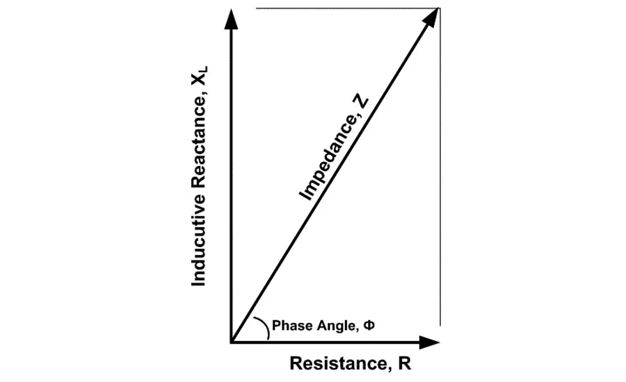
The resistive and inductive elements of the impedance are considered “out of phase” with each other. Figure 2 shows a graphical vector representation of the impedance (Z).
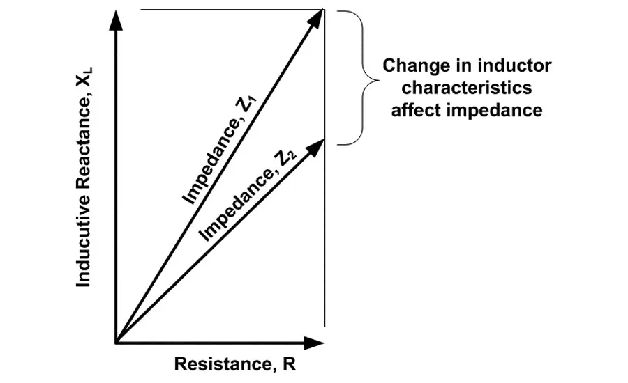
When the characteristics of the inductor changes, or the frequency of the AC signal changes, the inductive reactance (XL) changes. This causes the overall circuit impedance to change. Figure 3 shows what two different impedances might look like if the characteristics of the coil were to change. This forms the basis for understanding how we use eddy current testing to verify heat treat and alloy, or overall “material structure.”
Applications to Eddy Current Testing
A basic eddy current system consists of an eddy current instrument and eddy current probe. The eddy current instrument provides the AC signal that drives the probe, as well as the electronics to read the voltage output. (See Figure 1) The eddy current probe consists of one or multiple coils which form inductors. The wire that is used to make the coil has a small resistance, so the probe can be modeled as having an impedance as seen in Figure 2.
In eddy current testing, we place an eddy current probe next to a metal object to be tested. The proximity of that metal causes the impedance of the coil to change. Metals with differing material structures, due to differing alloys, differing heat treat, or even geometry, will change the impedance of that coil.
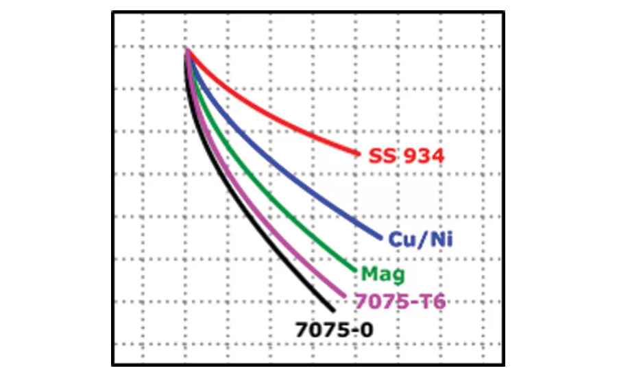
Figure 4 shows the impedance changes (on the X-Y plane) based on different materials and alloys. This particular test was done with an eddy current spot probe. The point in the upper left hand corner where all the curves come together is the impedance of the coil in air. It’s easy to see the impedance effects from the different materials and alloys.
An eddy current probe can also be configured as a transformer with a primary coil/winding and a secondary coil/winding. Figure 5 shows a “part under test” acting as the core of the transformer. A part with a different material structure will change the impedance of the transformer, causing a shift in the voltage out which is read by the eddy current instrument.
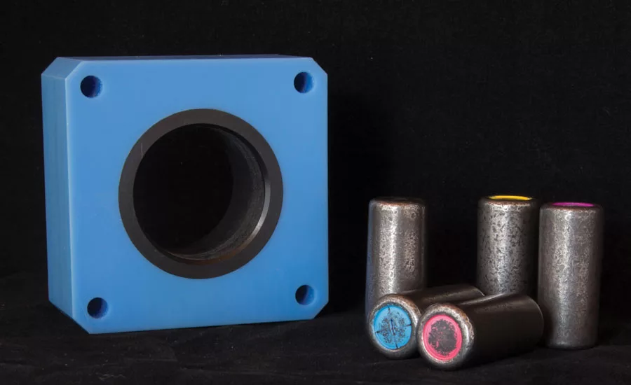
The eddy current probe in Figure 6 contains two coil windings (primary and secondary) wound in a transformer configuration. The two coil windings are wound around the center black bobbin in parallel with each other. The small roller bearings shown in the bottom right of the photo are the parts being tested with this eddy current probe. When the parts are inserted in the probe, they act as the core of the transformer. When running the actual eddy current test, it is important to place the parts consistently within the probe. The readings are so sensitive that a slight variation in placement can affect the testing results.
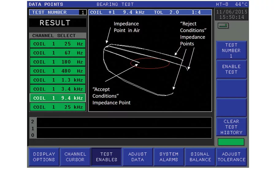
Just as we looked at the impedance curves for different metals in Figure 4, we are able to plot the impedance curves for four roller bearings with different hardness characteristics. Figure 7 shows an eddy current instrument display with those four different impedances. The impedance point in air is seen in the upper left. The “reject conditions” are shown to the far right of the red alarm zone. The “accept condition” reading is shown inside the alarm zone, which indicates a “good/passing” test condition. (Note that an alarm occurs when the point is outside the red ellipse).
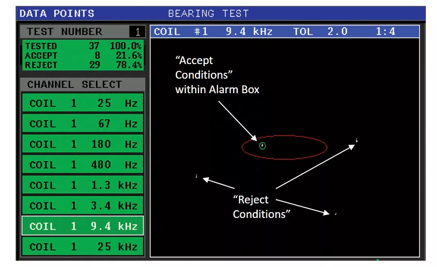
Production eddy current testing is usually performed by looking at the end point results. Figure 8 shows a typical eddy current test screen with a “good” result shown inside the red alarm zone. “Reject” conditions fall outside of the alarm zone. When a reject condition occurs, the eddy current instrument can activate industrial I/O which typically drives a reject mechanism on a material handling system.
Alarm zones are usually created by running a number of “good condition” parts through the probe and adding a small buffer area around the cluster. Although not necessary for initial setup, it is recommended that parts with known “bad conditions” are run and checked to ensure that they fall outside the alarm limits.
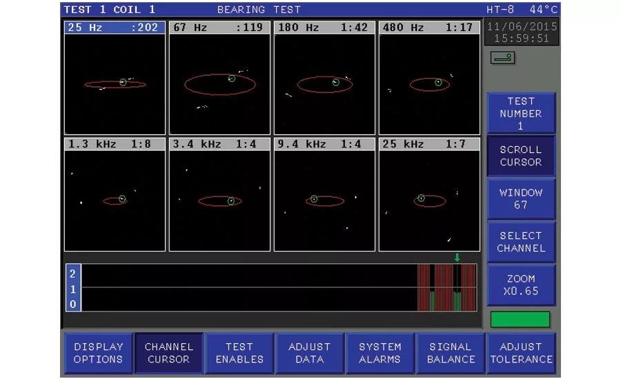
Different “reject condition” test results can occur at different test frequencies. This occurs because the inductance of a coil is dependent on the frequency of the drive signal. A typical eddy current heat treat/structure test will be run at eight unique frequencies to find varying product anomalies. The test parts run in Figure 8 were run at eight frequencies from 25 Hz to 25 KHz. The test screen shown indicates the results for 9.4 KHz.
Figure 9 shows the testing results from all eight test frequencies. If the test “fails” at any of the different frequencies, the entire test fails and the industrial I/O will drive a sorter to reject the part. Eddy current testing is a fast, and all eight frequencies can be tested in under a second.
Conclusion
Eddy current testing for heat treatment process verification is not magic, but is based on solid electromagnetic theory and implemented using modern electronics. While eddy current testing does not deliver actual hardness readings, it can often identify parts that differ by only a few Rockwell points. It is a fast, repeatable test that integrates well into factory production lines.
Dan DeVries is the director of marketing at Criterion NDT. He has 15 years of nondestructive testing and eddy current systems development experience, and has a MS/BSEE and MBA. He can be reached at [email protected].
Looking for a reprint of this article?
From high-res PDFs to custom plaques, order your copy today!


