Optics 101: Theoretical Foundations
A good grounding in the fundamentals of optics will help you efficiently apply optical technology to your own inspection needs.
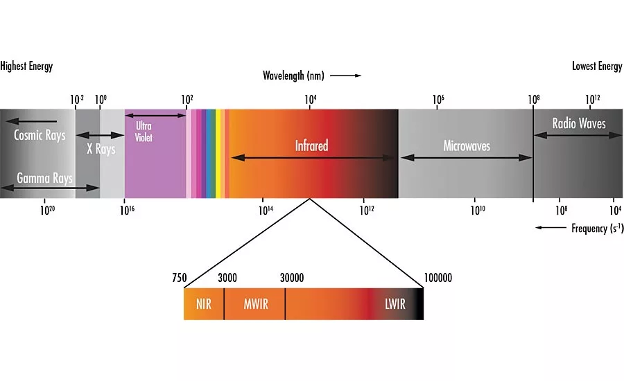
Figure 1. The electromagnetic spectrum stretches from high energy, short wavelength gamma rays to low energy, long wavelength radio waves. Source: Edmund Optics
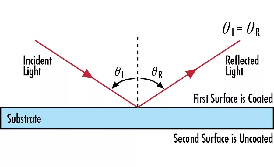
Figure 2. Light that hits a reflective surface at a given angle with respect to the normal to that surface will reflect off at the same angle in the opposite direction. Source: Edmund Optics
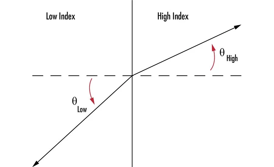
Figure 3. Refraction is a bend in the direction of light travel when transitioning from one medium to another. Source: Edmund Optics
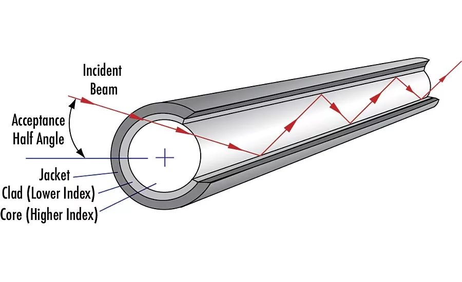
Figure 4. Total internal reflection keeps light confined to an optical fiber as it propagates. Source: Edmund Optics
Optical technology brings powerful capability to a wide range of problems. Imagine, for example, that you hold a blank piece of white paper up to the night sky. By measuring the intensity of light on that paper you could computationally reconstruct the image of all the light sources that created the intensity pattern. That type of problem is called the inverse problem, and it’s notoriously difficult to solve. But you can solve it simply by putting a lens in front of the piece of paper, which creates an image of the stars above.
Optical systems bring the same kind of convenience and power to other applications. A component measurement that would require eight different caliper measurements can be replaced with a single image. Alignment issues that would otherwise require a complicated measurement structure can be solved with a laser and a few simple optics. Visual inspection of product size, quantity, or fill level can be performed by a ruggedized camera and straightforward image processing software.
A good grounding in the fundamental underpinnings of optics will help you fully understand and efficiently apply optical technology to your own fabrication and inspection needs.
The Electromagnetic Spectrum
Light is a form of electromagnetic radiation, where linked electric and magnetic fields vary at a given frequency, which implies a given wavelength as well. That is, light of a specific frequency also has a specific wavelength, so knowing one of those values determines the other. Electromagnetic radiation travels at the speed of light, and the range of possible wavelengths is somewhat arbitrarily divided into different regions. Wavelength is often represented by the symbol lambda (l).
The longest wavelengths are grouped under the term “radio waves,” while the shortest are referred to as “gamma rays.” In between we have x-rays, ultraviolet, visible, and infrared. To some purists, “light” refers only to the very narrow region of the electromagnetic spectrum that is visible to the human eye. Most people, however, extend the term to include ultraviolet light and at least some portion of the infrared spectrum. Wavelengths of light are commonly measured in nanometers (10-9 meters, abbreviated nm) or micrometers (10-6 meters, µm). You’ll also hear micrometers referred to as microns (µ).
Figure 1 introduces some of the spectral regions of electromagnetic radiation defined by the ISO. Ultraviolet (UV) rays are commonly defined as between 1 and 400 nm. Visible light consists of the colors we see, at wavelengths between 400 and 750 nm. Infrared (IR) radiation, between 750 nm and 1000 µm, is often further divided into near-infrared (750 nm – 3 µm), mid-wave infrared (3 – 30 µm) and far-infrared (30 – 1000 µm)—this last increasingly being referred to as the “terahertz region.”
Each region of the spectrum has unique properties, interacting with materials in different ways. A lens that works perfectly for visible light, for example, is unlikely to be transparent to most ultraviolet and infrared radiation.
Reflection and Refraction
Light incident on a material can do one of three things: it can bounce off, go through, or be absorbed. Light that bounces off is categorized as reflection. Light that travels through a material is not unchanged; it undergoes a process called refraction. Light absorption is essential for its usefulness—if it weren’t for light absorbed in the retina, for example, we wouldn’t be able to see anything. Light absorption, however, is the final step in an optical system, so it doesn’t figure more in this discussion.
Reflection
The reflection of light from a surface follows a very well-defined rule. The law of reflection states that the angle at which light will bounce off a reflective surface is equal in magnitude to the angle at which it hit the surface. More formally, as shown in Figure 2, the angle of incidence is equal to the angle of reflection. Figure 2 illustrates reflection from a first surface mirror—a material with a reflective surface, either because the bulk material is reflective or because it had a reflective coating deposited on it. For a smooth reflecting surface the reflected light will all come off at the same angle. That’s called specular or regular reflection. If the surface is rough, the reflected rays will scatter; this is referred to as diffuse, or irregular, reflection.
Refraction
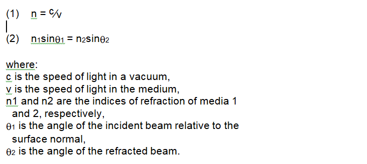
Light slows down as it travels through any material. The speed it travels through the medium depends on the wavelength of light and the properties of the material. The index of refraction, as in Equation 1, is the ratio of the speed of light in a vacuum divided by the speed of light in the material. The slower speed in the medium leads directly to the effect of refraction: the bending of light as it transitions between one material and another. A relation known as Snell’s Law, shown in Equation 2, describes the refraction. Figure 3 shows the geometry of refraction.
When light refracts from a high-index medium to a lower index medium, it’s possible that the angle of incidence can become large enough that the angle of refraction reaches 90°. At that incident angle, called the critical angle, light reflects back off the interface of the higher index material in a phenomenon called total internal reflection (TIR). As shown in Figure 4, total internal reflection is responsible for the propagation of light through optical fibers.
Dispersion
As mentioned above, a material’s index of refraction is wavelength dependent. Dispersion quantifies that variation in index of refraction. Because the index is different for different colors of light, those distinct colors will be bent differently in a process called chromatic aberration.
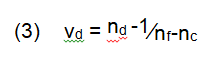
One way to quantify dispersion is to express it by Abbe number (vd), a function of the refractive index of a material at the f (486.1nm), d (587.6nm), and c (656.3nm) wavelengths of light (Equation 3).
Chromatic aberration caused by dispersion is responsible for the familiar rainbow effect seen in optical lenses, prisms, and other optical components. Dispersion can sometimes be a highly desirable phenomenon, as when using an equilateral prism to split light into its component colors, but it can be detrimental to a system’s performance in other cases.
The Beginning of the Story
This introduction has outlined the subset of optics called geometrical optics. Geometrical optics treats light as if it always travels in straight lines, a reasonable and useful approximation for most imaging applications. There is another subfield of optics called physical optics that deals with a more complex optical model, describing the phenomena of interference and diffraction.
Looking for a reprint of this article?
From high-res PDFs to custom plaques, order your copy today!


