Maximizing Computer Vision Image Quality with Automated Active Sensor Alignment
Machine vision applications are seeing a shift to high quality, high dynamic range sensors.
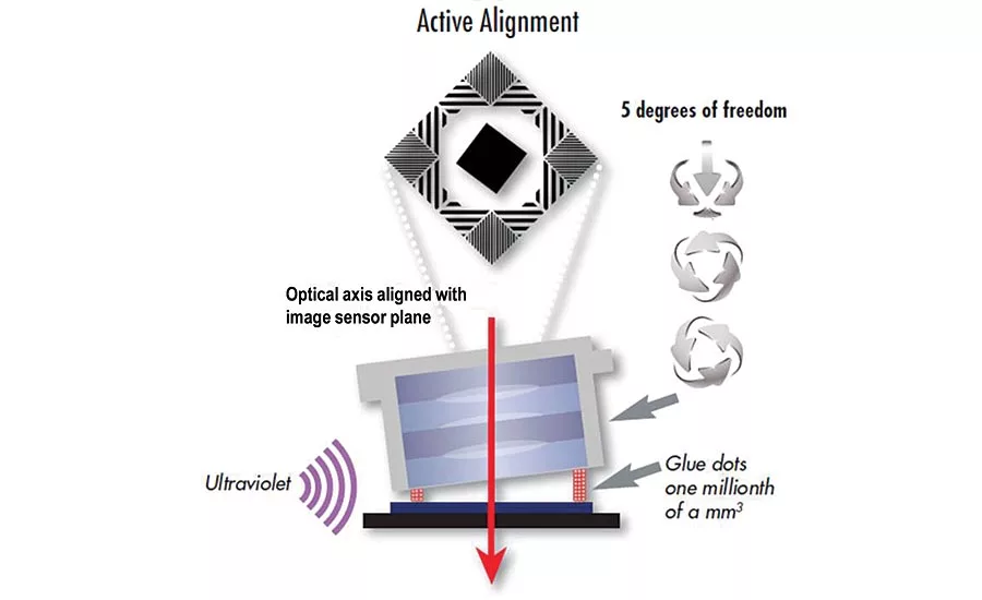
Active alignment of lens/sensor to 5-6° of freedom. Source: AEi
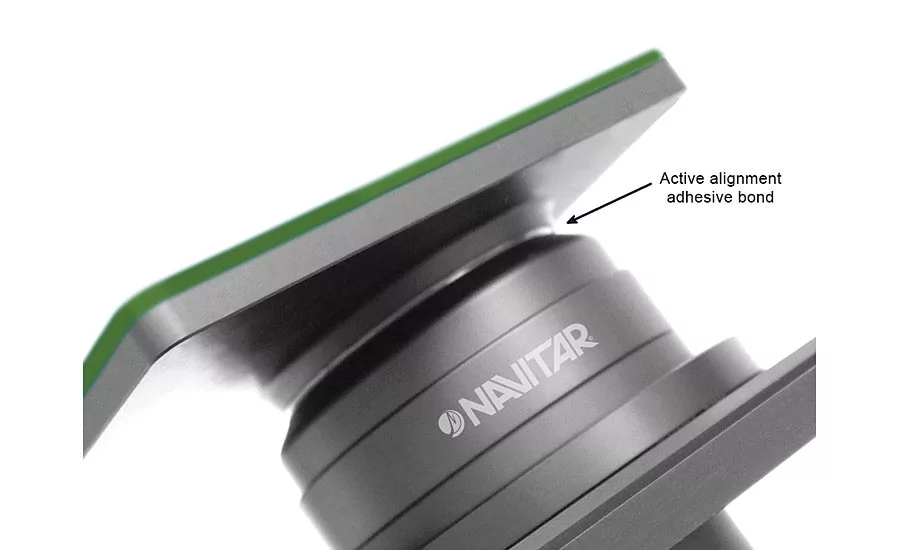
Active alignment adhesive bond of lens to sensor board. Source: Navitar Inc.

Figure 1. MTF Field Map (145lp/mm) with 0.25 Degree Sensor Tilt (50 Micron Runout)
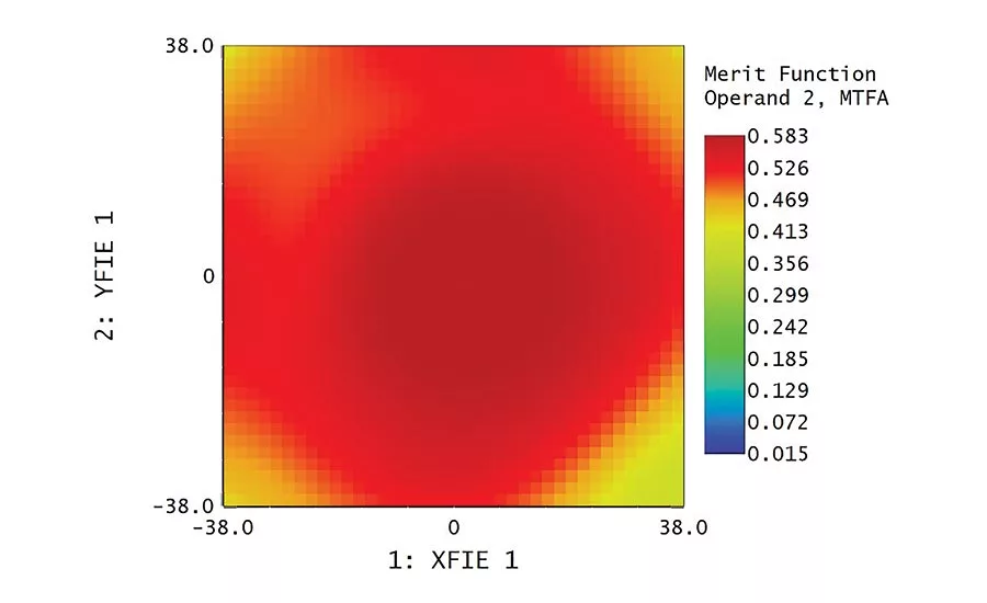
Figure 2. MTF Field Map (145lp/mm) Post Alignment (6 Micron Sensor Runout)
New computer vision applications are obtaining maximum image quality by combining high resolution, low-flare lenses with large format, high resolution global shutter sensors. Applications such as mobile mapping, UAV based inspection of power lines or facilities, and advanced automotive ADAS systems now require large field of view, high N.A. optics coupled with high resolution, high dynamic range CMOS sensors. To achieve maximum quality from a lens/sensor module, and produce these units efficiently and consistently, the use of automated active aligning machines is becoming more and more common.
Current CMOS global shutter sensors balance high resolution and high dynamic range by combining large pixel dimensions of 3.45 microns, which is a Nyquist frequency of 145 lp/mm. Manufacturing cost-effective lenses that consistently achieve high MTF (>40%) at this Nyquist frequency is a challenge. Even as manufacturers make these high performance large format lenses available, it is easy to forfeit the benefits of high MTF when the lens/sensor alignment tolerances are not optimal.
Six Degrees of Freedom
The consumer imaging space is driving the need for better quality, lower cost optical systems. Requirements for high resolution lenses, specifically for use in automotive ADAS systems, have increased the demand for high performance lens/sensor modules. The challenge to consistently produce high quality lens/camera or lens/sensor modules is the ability to optimize focus of the lens to the sensor in six degrees of freedom. This task is difficult to perform manually, requires trained operators, and suffers from the inconsistencies of human inspection.
The solution for the consumer electronics market is the use of automated alignment machines that actively align the lens/sensor combination using algorithms to optimize peak focus as well as tip/tilt of the sensor.
Even if a lens has a very high MTF, manufacturing errors can generate slight field tilt in the lens. Meaning, the optical axis of the lens will be slightly deviated from the mechanical axis, thus impeding the ability to achieve optimal MTF. Making a lens without this field tilt is possible; however, it requires more sophisticated lens fabrication methods, which add significant costs to the optics. Conversely, it is also difficult for camera manufacturers to achieve perfect alignment of a sensor to the mount.
Nearly every production line for smart phone cameras and automotive ADAS systems use active alignment robots to quickly and cost effectively produce modules for consumer grade products. The process is so efficient that the smartphone camera has now become the leading device for acquiring images for most consumers.
Machine vision applications are seeing a similar shift to high quality, high dynamic range sensors that achieve fast frame rates and use global shutter to capture large frame images. Higher frame rates result in increased throughput without the distortion effects seen when using a more traditional rolling shutter sensor. In addition, these new global shutter sensors use larger pixel sizes than consumer cameras—meaning the sensor size increases as the resolution of the sensor is increased. It is becoming more common to see applications utilizing area image sensors that require lens image coverage up to 17.6mm. This greater sensor area allows for a much larger inspection region and drastically improves the throughput achievable with smaller sensors.
Aligning Large Optical Systems
Actively aligning these larger sensors ensures maximum MTF is achieved across the entire field of view with no soft areas of the image (which will degrade the accuracy of image processing algorithms). The process involves loading a large format sensor into the alignment robot and being able to read a live signal from the sensor via electronics in the machine. The lens is plasma treated to remove any surface dirt or oil to achieve the best bond possible. Then a bead of adhesive is applied to the sensor carrier and the lens mechanically moves into position within the focus tolerances predicted during the design. The adhesive choice and post cure characteristics are critical to aligning large optical systems to large sensors because there is significantly more bond area than small, smartphone applications.
The alignment procedure finds best axial focus and then predictively iterates the tip/tilt, rotation and lateral adjustment of the sensor until achieving maximum MTF across the entire sensor. With the sensor in place, the adhesive can be spot cured with UV illumination and then either heat or time cured off-machine.
Maximizing Image Quality and Throughput
For example, an F/1.9 optical system is used to evaluate an outside scene for monitoring objects that only cover a few pixels. This application requires high MTF values at the 145lp/mm Nyquist frequency of the sensor. The sensor is square format and the wide angle lens has a 72 degree field in both the horizontal and vertical directions. The map in Figure 1 shows the 2D MTF across the sensor assuming a residual tilt of 0.25 degrees (±50 microns of sensor runout). Clearly MTF at 145lp/mm is significantly degraded with this amount of runout and will result in a substandard image to present to the vision system. Errors of this magnitude are possible based on the placement of the sensor on the ball grid array, misalignment of a mechanical lens flange, and positioning of the sensor board in the camera housing.
This MTF map can be significantly improved with active alignment, reducing the residual sensor error by 10x (~50 microns to 10 microns). In Figure 2, the MTF across the entire field exceeds 40% at the Nyquist of the sensor and the MTF across the entire sensor now exceeds 40%. This alignment process is very repeatable and can be performed rapidly in a high production environment.
Additional Benefits
In addition to improved optical performance, the adhesive bond will keep the lens module more stable as temperature and vibration influences the package. Mechanical mounting is likely to misalign over time when subjected to harsher environments.
Active alignment also has the advantage of improving the yield on high resolution, high N.A. lenses which are difficult to produce consistently in high volumes. In practice, most production lenses will have residual field tilt. Minimizing this tilt requires very stringent mounting tolerances on the optical elements to maintain a focal plane that is perpendicular to the axis of the lens. This may involve individually adjusting each lens in the stack to maintain a well behaved image plane. Allowing sensor tilt to be a compensator in the alignment process enables the optical designer to add some compensation of the image tilt and assign less stringent tolerances to some of the lens tolerances. This reduction in tolerances will improve the overall lens yield and therefore reduce the cost of the lens.
Active alignment of imaging modules, for use in higher N.A. computer vision and machine learning applications, ensures users will fully benefit from the advantages of combining high pixel density sensors and high resolution, large format lenses.
Looking for a reprint of this article?
From high-res PDFs to custom plaques, order your copy today!


