The New Science of Laser Trackers
Today’s enabling technology for “precision anything.”
Laser trackers are utilized in diverse manufacturing and scientific industries for large volume scanning and probing to more traditional work such as alignment and tooling.
The manufacturing industry continues to push the conventional boundaries of creating larger and more complex parts. The potential for costly errors also increases exponentially when producing large-scale, intricate components and assemblies. This emerging trend first initiated the idea of embedding metrology at touch points throughout the manufacturing process. What if a large part could be manufactured in a single process, and completely inspected and verified before it leaves the machine? What if this operation could be accomplished using a commercial-off-the-shelf (COTS) robot?
Theoretically, it would be possible for a simple robot fixed on a rail to perform tasks that would typically require expensive numerical control (NC) machines, but this scenario breaks down when the parts are more than 20m long. Large COTS robots, especially when attached to overhead gantries or rails, are not nearly accurate or repeatable enough to perform such tasks. Additionally in this concept, the robot would need to employ an established metrology grade inspection process to verify the part is being manufactured within tolerance throughout the entire process, and produce an inspection report before the part leaves the manufacturing cell.
Laser Tracking Advances
So you thought this article was supposed to be about laser trackers? It certainly is, as laser trackers provide the fundamental technology that makes the concept above possible. Laser trackers were first developed in the late 1980s. The goal was to build a device that had laser interferometer accuracies but did not require the complex fixturing that went along with linear interferometry solutions.
Prior to the introduction of laser tracking technology, large assemblies were either laid out with optical tooling (such as a jig transit or optical level), while other technicians used tight wires that were stretched between two points with a series of plumb bobs. All of these devices worked in either one-dimensional or best case two-dimensional space. Although these techniques were acceptable when no other options were available, they all had the limitation of operator dependency. Using a human eye to line up parts has an inherent error that simply could not be eliminated.
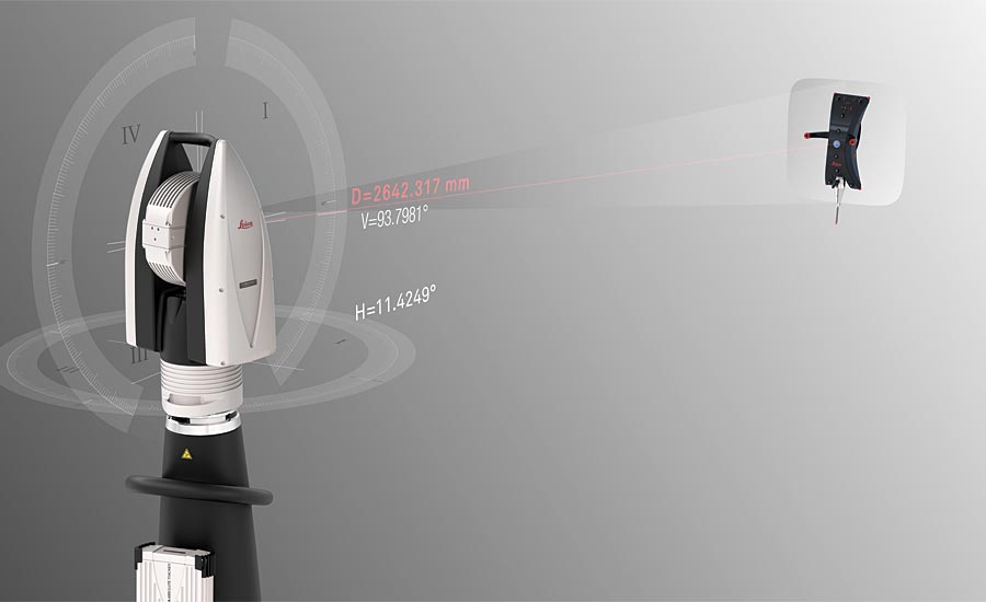
Instead of using an operator’s eye to “see” a value, a laser tracker relies on a laser interferometer. A laser that measures distance is projected from the tracker which can measure and drive horizontal and vertical angles. The laser is aimed toward a retro reflector device where the beam is then returned to the tracker allowing the two angles and a distance to be calculated as a 3D coordinate. The reflector can be moved freely and tracked within an area, while the laser tracker is constantly calculating its three-dimensional position at up to 1,000 times a second. Even though the first commercially available laser trackers entered the market in the early 1990s, they did not find their home in imbedded metrology until later down the road. Much of this success was tied to the laser tracker’s ability to measure with six degrees of freedom or 6DoF, which describes the freedom of movement of a rigid body in 3D space.
The T-Cam tracked a series of LED targets on the measurement end effector. The LEDs were used to calculate pitch, roll, and yaw, while the reflector and the laser were used to calculate X, Y, Z coordinates.
6DoF Measurement
The emergence of robotics in manufacturing immediately challenged the idea of measuring only in three dimensions. This market trend forced manufacturers of laser trackers to account for and measure all six degrees of freedom. Laser tracker technology acquiring X, Y, Z coordinate data also needed to account for i, j, k (pitch, yawl and roll) rotational data.
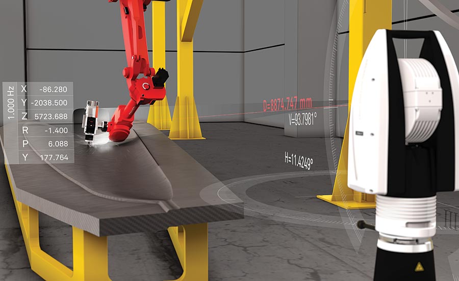
To accomplish this task, a photogrammetry camera was added to the top of the laser tracker. The camera tracked a series of LED targets on the measurement end effector. The LEDs were used to calculate pitch, roll, and yaw, while the reflector and the laser were used to calculate the X, Y, Z coordinate. This combined photogrammetry and laser tracker solution provides the best of both worlds. Because the camera uses a full-range “vario-zoom” lens to keep the field of view of the end effector both zoomed in and focused throughout the entire measurement range of the device, the rotational accuracies remain almost linear over the full measurement volume.
This advancement expanded the use of laser trackers in new applications where 3D coordinate data did not provide enough information. The ability of the laser tracker to capture all 6DoF movements allows the device to be measuring in one area of the robot (i.e. near the end effector) while the calculated tool center point (TCP) is being recorded. This major capability gives integrators the ability to compensate robotic solution when the beginning (joint 0) is stable. However, what happens if the base of the robot is on a 7th axis slide and uncontrolled? Even worse, what if the robot is hanging overhead on an unstable bridge construction?
In a real-time control loop, the planned trajectory of the machine is constantly monitored by a laser tracker. As the end effector starts to move or drift from the desired path, the deltas are then fed back into the robot kinematics and the process repeats.
Real-time Machine Control
Manufacturers evaluating large-scale machining solutions have always compromised between cost, flexibility and accuracy. Current robotic machining solutions are cost effective and flexible, but they cannot achieve the accuracies of modern 5-axis machining centers. While these machines set the benchmark for accuracy, their cost and flexibility leave room for improvement. The limitation to a large-scale robotic solution is the rail or slide. These 7th axis rails allow robots to move through a larger work envelope.
The problem with linear tracks is that they exhibit a very “non-linear” behavior. A small amount of error at the base frame of a robot can cause a very large error at the TCP of the end effector. Even if a linear track is brought into near perfect alignment prior to use, it will still exhibit non-linear performance when factors such as wear and thermal expansion start to occur. After much research, it became very obvious that physical corrections and compensations would not be able to achieve the accuracy and volume demands required, so a new direction was required. Today, a laser tracker is used to drive the position of the end effector in real time, rather than depending on a predetermined correction.
A Real-time Control Loop
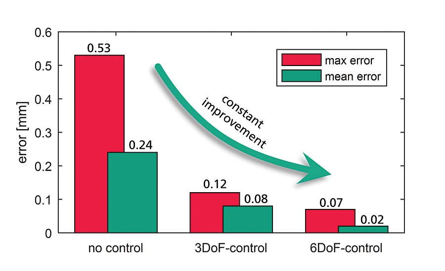
In a real-time control loop, the planned trajectory of the machine is constantly monitored by the laser tracker. As the end effector starts to move or drift from the desired path, the deltas are then fed back into the robot kinematics and the process repeats. In theory, this is possible at up to 1kHz, but most robot controllers today have around a 4ms limitation. The first test work done with a seven degrees of freedom (7DoF) laser tracker used a 12ms (83Hz) feedback loop to the robot. A test path was created based on the ISO 9283 standard to test the dynamic accuracies of this solution. The test path was measured with a path speed of 100mm/s in three separate conditions: 1) standard (no correction), 2) compensated and 3) real-time corrected.
Independent studies compared a dynamically guided robot versus a compensated robot (even in a small volume) and revealed potential for at least a 200% gain in accuracy. These results are even more interesting when an ISO 9283 test path was evaluated and the overshoot of the calibrated robot in the dynamic sequence could be visualized. The 7Dof corrected run showed dynamic errors < 0.1mm.
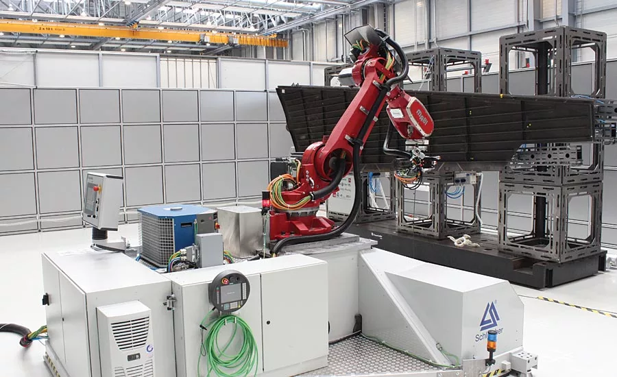
The MEGAROB project developed a flexible, sustainable and automated platform for high accuracy manufacturing operations in medium and large complex components using a spherical robot, a 7-DoF-enabled laser tracker and an overhead crane.
Down the Road
Laser trackers have come a long way since their humble beginnings nearly 30 years ago. A device that was originally developed to measure two angles and a distance to a reflector has steadily progressed toward a much larger and promising future. Today, laser trackers are utilized in diverse manufacturing and scientific industries for large volume scanning and probing to more traditional work such as alignment and tooling. This technology has evolved with the times to become the go-to solution in a metrologist’s tool box for taking on the contemporary challenges of manufacturing, robotics, and the smart factory. Q
Looking for a reprint of this article?
From high-res PDFs to custom plaques, order your copy today!


