Chatter Mark Inspection: Methods and Measurement Systems
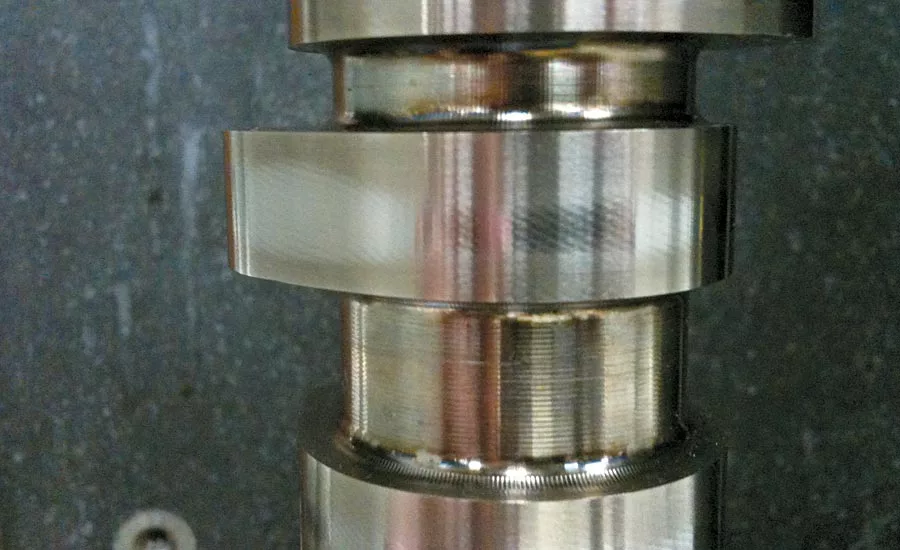
Here are examples of chatter marks (a.k.a. chatter).
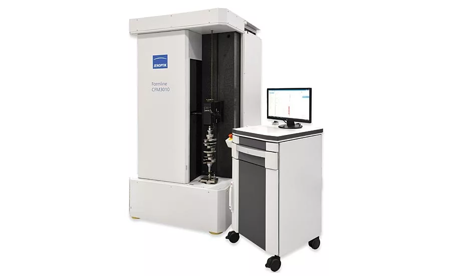
This is the Hommel-Etamic Shaftscan 1030.
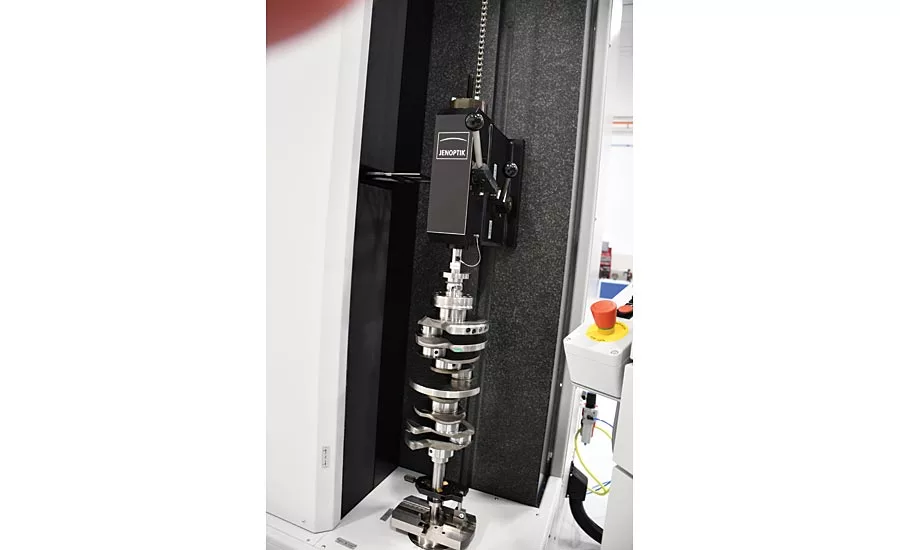
Part loaded between upper and lower centers
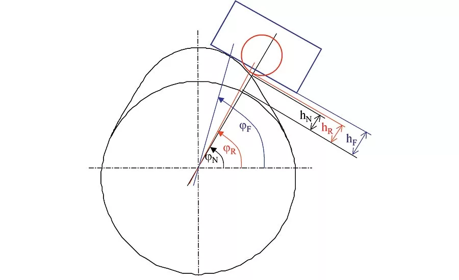
If the measuring follower of the measuring machine is not consistent with the geometry of the cam follower in the subsequent engine when measuring cam lift, the software converts to the specified radius.
The software facilitates measurement tracking on the screen. In addition to the numerical output of measured values, the warning limits are also displayed; these are shown in color to improve clarity.
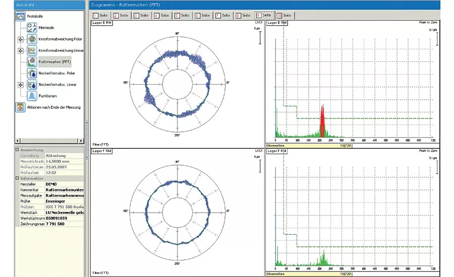
Chattermark evaluation of a workpiece with and without (upper) air bearing mechanics. Without air bearing mechanics, several tone bursts were recorded that originate not from chattermarks but from the measuring system itself. The existence of chattermarks can therefore not be reliably determined with this type of system.
As related to form metrology, a roundness measurement defines how closely the shape of a part approaches that of a perfect circle. This measurement is critical to the performance of any rotating shaft and particularly to the crankshaft and camshaft of an internal combustion engine. A measurement system, or gage, is used to monitor the part quality and store the roundness data. The measured roundness data is comprised of radial measurements made at regular intervals, from a defined part center.
For the purpose of applying a tolerance, a value for the roundness measurement is given as the worst case deviation from a perfect circle, expressed as a peak-to-valley displacement, from a defined part center. Roundness can also be referred to as “circularity” and sometimes “out-of-roundness.”
If we examine the roundness measurement data more closely, we find it is comprised of regularly spaced undulations, as well as random deviations. The regularly spaced undulations are imparted to the workpiece during the machining processes (milling, turning, grinding, polishing), by the clamping forces of the chuck, or by the steady rests (if present). The cause of the random deviations can be more difficult to attribute and may add or subtract from the amplitudes of the regularly occurring waves. To achieve effective root cause analysis, the frequency of each undulation must be separated from its counterparts, as well as the random deviations, and quantified.
The terms “lobing” (derived from “lobe”) and “chatter” (derived from “chattermark”) are often used to name the regularly occurring undulations in the roundness data. Low frequency undulations are generally referred to as lobing and high frequency undulations as chatter. However, when measuring a crankshaft or other rotating engine part, these terms have very specific definitions. The lobing measurement is performed by looking at the maximum peak-to-valley deviation of the roundness data, over a specified angular range. It is a “slice” of the measurement data and can be used to ensure that the total roundness error does not occur over a short arc. Multiple lobing sectors of varying angular ranges can be used to get an approximation of the lobing frequency.
At the time of this writing, many crankshaft manufacturers were still using lobing measurements in this way. However, because each angular sector can contain multiple frequencies, lobing is not particularly well suited as a method to measure frequency content. Although filters can be applied and multiple lobing windows employed, the lobing feature is better suited as a functional check than one to determine a root cause.
Chatter Mark Measurement
Unlike lobing, which is based on deviation in an angular window, chatter analysis is performed using a fast Fourier transform (FFT) to analyze the roundness data. This algorithm samples the data and divides it into its frequency components, each with its own amplitude and phase. The chatter measurements are shown as undulations per revolution (UPR) and plotted with their corresponding amplitudes.
Chattermarks on precision shafts, even at low amplitudes, can shorten the life of the bearing. On camshaft lobes the presence of chatter is more of a concern for NVH (noise, vibration, and harshness) than durability.
When measuring either lobing or chatter, attention must be given to choosing a filtering method. The automotive and aerospace industries have long employed filters of 5, 15, 50, 150, and 500 UPR as the standard options and care must be taken to ensure that the frequencies of interest are not removed or attenuated. High UPR cut-off filters are commonly used in lobing measurement, but it is preferable to use no filter on FFT/chatter measurement.
Even with low frequency, long wavelength undulations, using a Fast Fourier Transform (FFT) is a more useful approach if the goal is to isolate a problem frequency and locate the root cause. Isolating the frequencies that make up the total roundness error also allows us to apply tighter tolerances to specific UPR ranges. On a crankshaft bearing or journal, these tolerances will typically get tighter as the UPR frequencies increase. In other words, deviations that occur over a longer wavelength are less of a durability concern than those occurring over a shorter wavelength. If the manufacturing process produces a frequency that is typical, we can also apply a control tolerance to a specific frequency.
Gages for Chatter Mark Inspection
Chatter marks were traditionally identified by manually inspecting the ground surfaces under intense light. While this can be an acceptable method of inspection for chatter produced during milling or turning operations, it is generally not acceptable to find chatter produced during grinding. Visual inspection, either by human or machine vision, is inadequate for quality control on grinding operations because the frequency and depth of the defects cannot be quantified. Manual inspection is also fatiguing to the inspector and so, unreliable as a long-term solution.
When considering how to measure your crankshaft or camshaft, care must be taken to choose the right gage for these measurements. Optical gages relying on a camera system are limited because they cannot “see” the full peak-to-valley (laser spot gages can be employed if the spot size is small enough for the expected wavelength of the chatter). Point contact (tactile) methods are preferred to ensure that the full undulation is traced.
Form metrology gages are specifically designed to measure form errors such as roundness, lobing and chatter. An example would be a product specially designed with a long probe travel, to measure crankshafts and other shafts with eccentric features.
In Part 2 of this series, we will discuss the design requirements of a shaft gage that is suitable for chatter mark measurement.
Looking for a reprint of this article?
From high-res PDFs to custom plaques, order your copy today!


