Shaft Measurement: What is the Best Tool for the Job?
Shaft measurement can be performed with a variety of metrology tools, from handheld devices to high-end coordinate measuring machines.
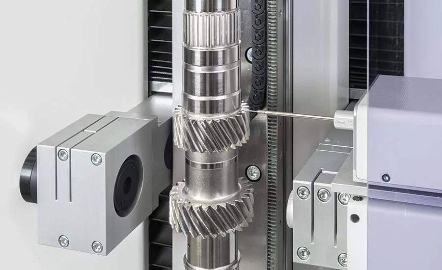
Measurement of a shaft with a gear on a multi-sensor shaft machine.
The simple shaft is one of the ubiquitous items in every mechanical system. Shafts contain a number of key functional elements, such as splines, tapers, grooves, threads, cams and gears, which all have associated critical dimensions to allow these mechanical systems to perform the function for which they were designed. Many of the diameters, lengths, angles, distances between points and lines, groove widths, fillet radii, or chamfers on these parts are ideally suited for shaft measurement systems.
Designed to facilitate precision control of complex turned parts, shaft measurement systems are ideal for automotive, aerospace, and medical industry applications, to name a few. Given the fact that the shafts used in these types of applications are often safety- and performance-critical, ensuring precision, quality and high reliability is of the utmost importance.
Shaft Measurement Trends
Ever-increasing accuracy requirements and declining cycle times are creating the need for rapid, precise measurement directly in the production environment. As shaft measurement systems have grown in popularity, the market has demanded increased capabilities.
Trends shaping the demand for advanced shaft measurement technologies include:
- Decreasing tolerances
- Increasing demand for more precise measurements
- The need to move measurement closer to the manufacturing process
- The need for increased speed and economy in production lines
- The need for more automation of the measurement process
- User requirements for integrated systems to provide feedback directly to machine tools
- Greater ease of use
Optical Shaft Measurement Technology
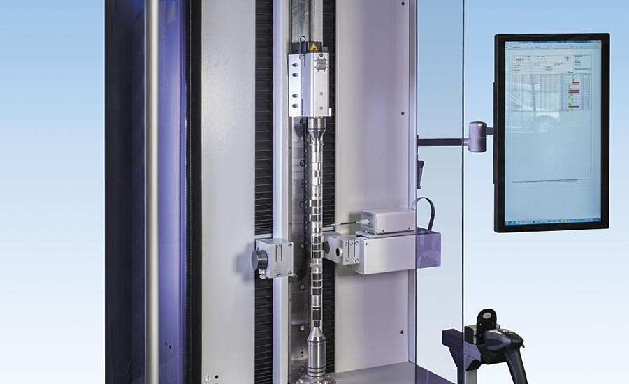
These market demands have led to the rise of advanced, fully automated optical shaft measurement systems that offer efficient and precise measurement of rotationally symmetrical workpieces in production. These systems also enable highly accurate measurement of a wide variety of characteristics in just seconds—without operator contact. Fully automatic measuring sequences can be performed both in the lab and in the harsh environment of the shop floor, and eliminate operator influence from measurement results. These benefits of high measurement speed, precision, and optimum ease of use in a noncontact process ensure the utmost in quality control during production.
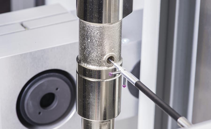
Measurement of blind holes isn’t possible with optical sensors, so the tactile probe combination is the ideal solution.
There are two commonly used technologies in optical shaft measurement systems: high-resolution matrix array, or CCD cameras, and line scan technology. Line scan technology creates images of the dimensions of the part via cameras that contain a single row of pixels. As the object moves past the camera, the image is reconstructed line by line. Line sensors are often tipped slightly relative to the axis of the part to better measure dimensions such as edges and shoulders. Part and feature diameters are indicated as a series of connected points or dots, and measurement computations are made with a “calculated” image of the part. Because of the lower resolution, small features are harder to measure.
High-resolution matrix array is a more modern technology that was made possible by advances in computer processing speed. The higher resolution of matrix array has earned these systems a reputation for being the most accurate method because they enable measurements to be more stable and precise, and allow much smaller features to be measured compared to the calculated image produced by a line scan. Zoom functions further allow even the most minuscule details to be measured, which with conventional measuring methods are difficult—if not impossible—to test.
While matrix array measurements were previously seen as a slightly slower option to line sensors (due to the larger amount of data processed) a number of advancements, including faster processing time and measurement optimization programs, are quickly closing that gap.
Processing time has been sped up not only as a result of faster processors, but also the controllers that run them. Optimization routines are also utilized in newer, advanced systems to make the measurement process faster. Previously, a machine was moved to a certain location to take a picture. The area of interest (AOI) was defined within the picture where an edge, radius or other feature was expected to be found. The process was repeated for each feature to be measured and the program would analyze the data within each AOI to determine the results.
With advanced optical shaft measurement systems, once the programming is finished, the system runs an optimization program that looks at the AOIs and determines, for example, that if several AOIs are close together they can all be captured in one image. The older system would have taken separate images whereas advanced systems can do the same with one image. These systems will also optimize the movement in between image captures to cover the minimum distances between locations.
What About Features that Can’t Be Measured Optically?
Despite the many benefits of optical technology, it can only see what is visible from the outside; the measurement process typically involves backlighting the part and obtaining a silhouette image for measurement. However, there are a number of elements that simply can’t be seen in silhouette.
For example, camshafts and gears naturally go along with shafts. The cams control the inlet and outlet valves in every combustion engine. There are also features such as keyways, shafts with splines on the end, gear teeth, and more that don’t readily lend themselves to optical measurements. Complete testing of these types of workpieces is becoming increasingly important because whenever tolerances are exceeded without detection, entire assemblies often break down.
To perform these required measurements, two separate machines, setups and processes have typically been used; an optical shaft measurement tool and a tactile measurement machine to handle all of the features that can’t be measured with the optical system. Today, there are new technologies emerging that offer a combination of optical and tactile sensors, including a high-precision matrix camera and 2D probe system. These enable the complete inspection of parts such as camshafts and gears in one setup.
This type of measuring solution has several advantages. The automated measuring procedure is much faster and much more reliable. While conventional coordinate measuring technology takes approximately 30 to 40 minutes per workpiece, this new technology can measure a four-cylinder camshaft in just five minutes, and a shaft with a typical helical gear in 5-10 minutes depending on the number of teeth checked on the gear.
Furthermore, the measuring station can be used directly in production at the machine tool for the respective machining operation. The motorized tailstock ensures that the workpieces are always clamped with the same clamping force and thereby eliminate operator influence. Furthermore, the system has complete 3D functionality as the tactile and optical measuring systems are calibrated together and operate in the same coordinate system.
For camshafts such as this, an optical sensor is ideal for many length and diameter dimensions. However, in order to capture the cam lobe profiles accurately, the tactile probe is used.
The Benefits of an Intelligent, Integrated Operating System
One of the most critical aspects that all measurement tools can ultimately provide is valuable data that results in actionable intelligence. For maximum impact, every measurement machine in the production environment should deliver data in a standard format such as statistical process control (SPC) reports—and conform to a standard unified measuring language so that any operator can be easily trained on a single standard interface across machines.
Software is a huge differentiator in terms of delivering valuable, actionable data and ensuring maximum ease of use. If all metrology systems in a manufacturer’s facility are modularized on an operating system level, they use the same basic command and interface structure, and therefore will essentially all operate in the same way. As a result, users can more easily utilize different types of measurement tools because the setup looks similar and the same basic steps are taken to control it. Data across all systems can also be exported in a single, standard format such as SPC reports, further maximizing its usability and value.
As a result of operators being trained on a single standard interface across machines, cross-pollination is possible: surface and contour measurements can now be taken on a form machine, and form and contour measurements can be taken on shaft measurement systems. This dramatically improves the entire dimensional measurement process and increases productivity.
In short, intelligent integrated operating systems enable all systems in a manufacturer’s line to operate the same way, minimizing training and maximizing ease-of-use. Time savings in writing and updating system software is an additional benefit.
Conclusion
Shaft measurement can be performed with a variety of metrology tools, from handheld devices such as micrometers and snap gages to high-end coordinate measuring machines (CMMs). However, specific shaft measurement systems can accomplish the required tasks significantly faster, with more precision, and do so directly in the production environment.
As the trend continues toward increasingly smaller features and tighter tolerances, shaft measurement devices that are easy to program, perform efficient and highly accurate measurements, and can accommodate a wide range of parts are increasingly becoming the method of choice for the measurement of rotationally symmetrical workpieces in production—ensuring the utmost in quality control during production. Q
Looking for a reprint of this article?
From high-res PDFs to custom plaques, order your copy today!


