Striving to New Heights
Today's height gages are feature-packed, high-performance measuring systems.
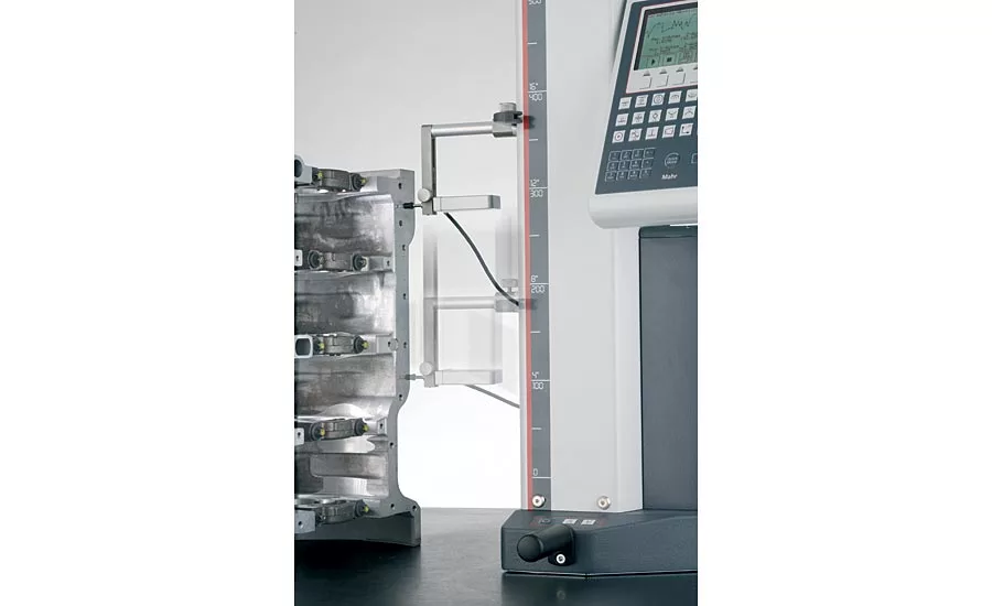
By adding a linear probe to the measuring carriage allows the height gage to perform squareness checks.
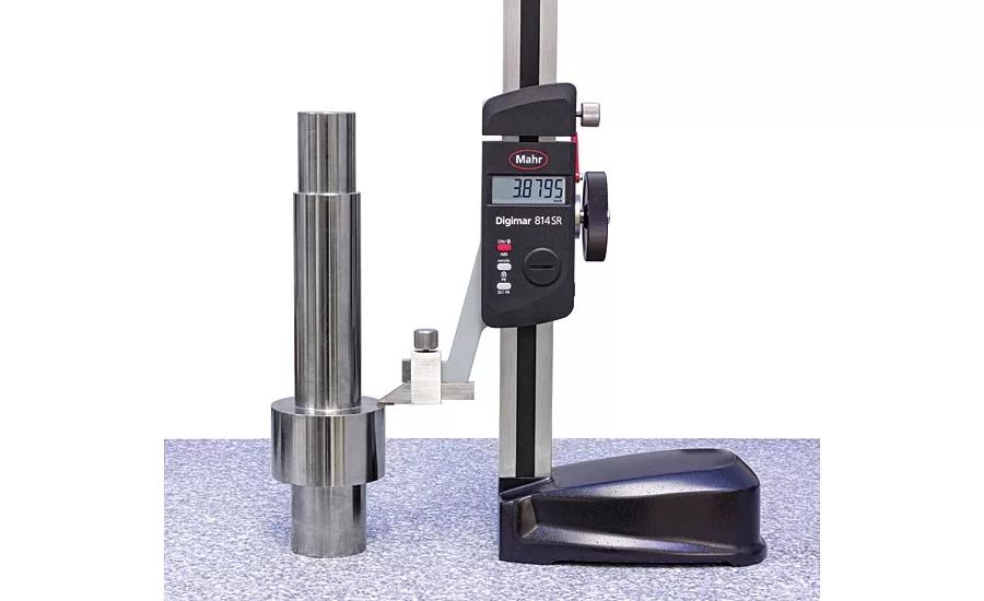
A scribing height gage can be used to scribe a dimension on a part to be machined or used as a simple length.
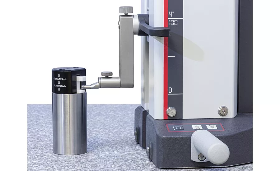
Simply by starting the probe towards the surface to be measured can initiate a measurement.
While a height gage can be used at the point of manufacture, it is important to ensure that the surface plate is clean and within tolerance, as it sets the reference for the measuring system.
While a height gage can be used at the point of manufacture, it is important to ensure that the surface plate is clean and within tolerance, as it sets the reference for the measuring system.
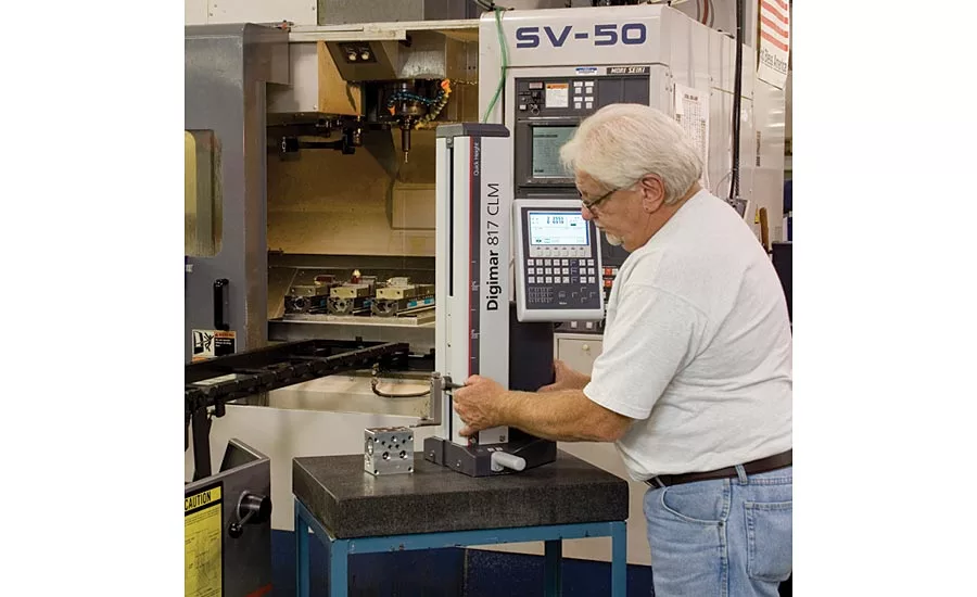
Choosing icons for measuring tasks makes use by the operator very simple.
The need for long-range height measurements has been around since the principles of lay out work became a fundamental requirement in machine shops.
The first step in the manufacturing process is to lay out a piece by transferring a design or pattern to a workpiece. This is performed in small shops, large manufacturing plants, and even by home hobbyists. The process may be used to begin a prototype piece or an emergency replacement part. The common tools for layout work include a surface plate, a surface gage with scriber or dial indicator, and a long-range height gage.
As with most inspection processes, the surface plate provides a reference plane for the part and the height gage. Height gages are then used to set and mark a certain height on the workpiece, or to measure the piece after it has been machined.
Types of Height Gages
The height gage is a conceptual extension of the handheld caliper gage, except that it rests on a heavy base that keeps the scale square to the surface. Height gages have a beveled pointer on the moveable jaw that can be used to mark or scribe the part. Alternatively, by setting the reference height on the base surface, the scribing point can be used to find a height characteristic on a part and display it on the gage’s readout.
There are four types of basic height gages. The classic Vernier height gage has been around for close to 100 years and is still used by machinists who feel really comfortable counting the grads to make sure their readings are correct. The circular scale height gage uses a dial indicator to set the measurement height. The digital height gage is a relatively recent addition that allows for direct reading of the height. Today, there are also electronic height gages with motorized drives that are capable of making various direct length or even 2D relationship measurements.
The first three height gages are primarily used for the layout applications mentioned above, setting heights to scribe a part or height measurements. However, for inspecting parts, an electronic height gage is the tool of choice due to its versatility and direct-reading measurement capabilities.
Obtaining Quality Measurements
As with any measurement, the quality of the result depends on the measurement instrument and the care with which the operator handles the procedure. Many gages are designed to make this as easy as possible. A snap gage, for example, has the reference anvil, frame and measuring instrument built in. The same is true with a height gage but because of the potential size of the measuring system, there are important outside considerations to be concerned with.
The typical size for height gages ranges between 350 mm to 1000 mm, but they are available in sizes up to 1800 mm. As you can imagine, there is an issue in making these long-range measurements as the size of the height gage increases. The primary issue that they have is what they measure—height. The larger the height gage, the bigger the potential problem.
However, it is not actually the height that is the problem. It is the relationship of a large height to the small base. Similar to a lever—the longer the arm, the larger the multiplying factor, is a problem. This involves not only the errors coming from the gage itself (post to base squareness, flexure or accumulative long-range scale errors) but also errors in the setup. These issues become magnified and can potentially distort an otherwise carefully planned comparison.
A common step in trying to increase the performance of the gage is to beef up the column in an attempt to reduce the flexure of the post. However, this is only part of the solution towards a better gage. For example, if a slight pressure is placed horizontally against the gage’s measuring contact, the gage may slide along the table. If the same force is applied to the measuring contact when it is near its maximum upper position, this force will very likely cause the gage to tip over. The base needs to be made longer and wider, with some mass built in. By decreasing the ratio of the post to the base, there will be significant improvement in its performance.
A bad reference is also a concern for a height gage. Most height gages are used with a surface plate. The surface plate provides the reference for the part and the height gage. Many surface plates are clean and well maintained, but there are those that may not be as clean as they look. A small metal chip or even a hair, while almost impossible to see, could throw off the measurement by parts of a micron at a height of only 250 mm.
Next to dirt, the actual granite surface of the plate will play a key role in the performance of the gage. Any slight imperfection between where the part and the gage are staged will be amplified the higher the measurement. For example, most surface plates have a flatness spec of 1um. If the base were 150 mm long, a 1um error would grow to more than a 6um error in 1000 mm, and even worse if the plate were out of spec.
Furthermore, height gages are direct reading measuring instruments (they have the reference scale built in) so they are especially susceptible to variations in temperature. Behind dirt and mechanical issues with set up, temperature is a significant influencing result. Since the body heat of the operator is clearly above room temperature (20 º C), any heat conveyed to elements of the measuring circuit (base plate, test piece, height measuring instrument, stylus) could cause local heat expansion and induce measurement errors. As a result, operators should be very careful in observing the following rules:
- Avoid touching the test piece with your bare hands directly before the measurement; use gloves.
- Do not touch other elements of the measuring circuit.
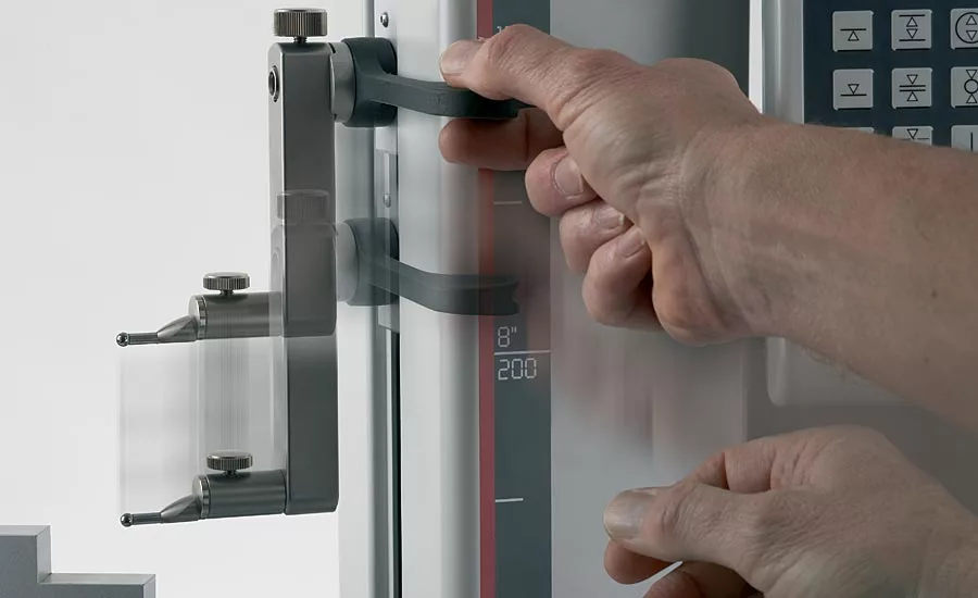
- Only touch the height gage at points provided for this purpose: handles are usually provided to move the gage or engage the air bearings for positioning.
- Avoid drafts.
- Avoid direct sunlight on the instrument, test piece, or base plate.
Completing the Measuring System
Now that dirt and temperature are controlled, we need to start thinking about completing the measuring system. Height gages are similar to dealing with a large digital caliper, so the same type of referencing process needs to be done. With a caliper, one would bring the jaws together. With a digital height gage, one needs to set the reference against the surface plate.
With automated height gages, this is done automatically whenever the gage is turned on. In a manually driven gage, the gage must be zeroed on the granite plate before it can be used. With a motor driven unit, the gage will automatically move down to touch the surface to set its reference point. It is not a bad practice to initiate this zeroing routine a second time, just to make sure that no dirt or other anomaly has introduced an incorrect reference. Since setting this reference is critical to all the measurements you will make, it is worth the time and effort.
The other important reference is the correction for probe ball diameter. If a height gage is to be used only for length measurements taken with the probe moving down, then probe diameter is not important. The contact point of the probe will be the same as in zeroing. But, if grooves, diameters, or hole locations are being measured, or if any measurements are taken with the probe moving upwards, then the probe ball diameter must be known and taken into account.
Ball diameter is specified for the probe, of course, but there is always some degree of variation. Actual ball diameter should be added to any dimension that is probed in the upward direction.
On height gages that have even the most basic electronic control this dimension can be measured as part of a set-up routine and is automatically included in all measurements. The automated process uses a fixture provided with the gage, or the test can be simulated with a couple of gage blocks. The fixture sets up a plane that is measured by the gage from both directions. The gage then looks at the difference between the two measurements and calculates this as the ball diameter.
The same gage block check can be done by hand on manual machines or the ball diameter may be measured off-line with a micrometer. Just as with setting the zero reference, this check should be repeated a number of times. Many gages will provide this repeat check automatically and reject the ball diameter reference if it does not repeat to within a preset limit.
Additionally, failing to recheck for ball diameter can be a deadly pitfall when a probe tip is changed. Going from a 10- to a 5-mm ball tip would be disastrous if not recalculated.
The Benefits of Electronic Height Gages
With the ability to auto-zero the gage on the surface plate and automatic calculation of the ball diameter, and using this as part of the measuring process, we are starting to get a flavor for the value of the electronics in the electronic height gage. As we know, operator influence is the next big enemy in measurement and there are features built into the electronic height gage to help reduce this.
For example, height gages with motor drives of the gaging probe tend to have improved performance by using a constant gaging force as the test piece is measured. This improves upon hand-wheel driven height gages as no two operators, or even the same operator, will have the same “touch” whenever the part is contacted with the probe.
Height gages measurement capabilities generally include:
- To measure the distance from a reference surface to a specific feature of a part to verify that it meets specifications and tolerances
- To scribe a part with accurate vertical dimensions or features from a datum plane so that additional machining can be done
- To verify center-to-center dimensions
- To measure diameters/slot widths
- To measure flatness
Since the gaging probe is motor driven, electronic height gages employ automated gaging routines to make dimensional measurements. Typically, there will be an icon representing the measurement to be made. Making a simple length measurement from above is done by raising the measuring probe above the part, bringing the arm into position below the part and selecting the “down measurement” icon. The gaging is being done in this automated measurement by driving the probe down onto the surface by its motor drive and once the part is touched (with the probes programmed speed and gaging force) it retracts and is ready for the next measurement.
Today’s electronic height gages will have similar icons for up measurements, slots, diameters and ID or OD radii. The difference with these diameter checks is that the part, or the gage, will be moved to “sweep” the diameter to find the high or low spot dynamically.
New features allow for making down or up measurements without the need for even selecting the measuring icons. By placing the probe over the part and starting to slide the probe arm down, the electronics sense a start of the measurement and will start the motor to make the down measurement. On a part with multiple length measurements, this can be a major saver for the operator.
While these relatively simple length measurements are fast canned operations, measurements that are even more complex are also automated with electronic height gages. Functions allow for dynamic measurements for flatness, straightness, angle measurement and perpendicularity when combined with a sensitive probe. Additionally, bolt circle patterns and hole sizes can be measured with the 2D function found in many electronic height gages.
However, this only begins to describe the measuring capabilities of the modern height gage. As measurements are made, they are stored internally, and from the measurement data, heights, midpoints, diameters and relationships are only a keystroke away. The measuring process performed can also act as a basis for a part program. Since every measurement and routine are stored on the gage, this past measurement history can be used as a new part program. Thus, when the part comes along again or there are a series of similar parts to be measured, this routine becomes the part program for repeating the measuring process. All these measured values can also be stored on a USB memory stick or the data can be sent via a cable or wirelessly to a PC for long-term storage or further analysis.
Conclusion
Today’s height gages are feature-packed, high-performance measuring systems. In reality, they can be thought of as single axis CMMs. Considering that they implement canned measuring modes, can store part programs, have the ability to use different probes with various contact configurations and diameters and have the ability to store/print gaging results, they really do have all the same capabilities as a CMM for a single axis. When used on a good surface reference, electronic height gages can offer substantial benefits in terms of time and productivity savings and high quality measurements on the shop floor, or as part of a receiving inspection area, at a price that offers high value for the results provided. Q
Looking for a reprint of this article?
From high-res PDFs to custom plaques, order your copy today!


