Surface Tools
Speaking the language of Industry 4.0

Digitalization has changed our world as the internet and modern technology continue to shape the manufacturing industry. For example, the vision of Industry 4.0 shows that production systems and machines are required to be flexible and adapt with continuously changing manufactured products. That means production will be more individualized, flexible, and faster.
All types of gaging, whether it be with hand tools, portable surface systems or complex metrology systems, went digital long ago. Many of today’s digital tools can perform complex measuring tasks and share data much faster than a decade ago. However, only now are they beginning to learn the language of Industry 4.0 and becoming able to communicate and share information to meet new demands.
For humans, language is the principal method of communication, consisting of words used in a structured and conventional manner and conveyed by speech, writing, or gesture. Unless those communicating speak the same language, the conversation can break down quickly and turn into non-communication. In the digital world, bits and bytes are the “words” shared between devices to communicate. And the same is true with communication in Industry 4.0—unless all the parts speak the same language, production can grind to a halt quickly.
As part tolerances tighten, surface finish has a larger influence on the size and function of the finished product. With pressure on manufacturing to be more productive, it is no longer viable for surface or form checks to be performed on a measuring system in a quality room. It is becoming more important to measure surface finish at the point of manufacture—often by the same machinist who is responsible for manufacturing the part. Or, more aptly, by semi-automated or fully automated surface gaging systems that are communicating with the user onsite—or maybe even thousands of miles away.
While this person is often an expert on running the machine, he or she is not necessarily an expert on making surface finish measurements (as well as related tasks such as collecting and documenting data). This is evident today since many handheld mobile surface systems now have a laboratory-grade surface finish system.
Operator Ease Of Use
The latest portable surface gages interface with the user just like a smartphone. They require very little operator training and can be used in minutes. Still, machinists are under a lot of production pressure and in Industry 4.0, production will be more individual, flexible, and faster. To the machinist and user of the surface system, this most likely means new surface finish parameters, tolerances and setup information for each new part manufactured. Even with the simplest surface finish system, there are literally hundreds of possibilities in setup parameters.
In the past, most surface systems were communicating in only one direction—sending data out for recording. Now devices are becoming capable of receiving information as well—specifically, setup information.
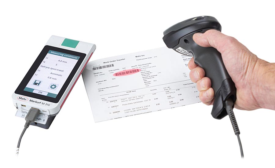
Figure 1: Measuring systems can be used in conjunction with handheld scanners to allow for parameter settings that can eliminate operator influences. Source: Mahr
Machine and CNC inspection tools have been able for some time to read barcodes that contain or bring up the proper setting for a part. The same is now happening with portable surface finish systems. The work order documents for the next set of parts the operator is to machine contain a barcode identifying all the setup parameters for the surface finish gage. The user can simply scan the traveling documents and the system is ready to measure the next part—with the specific parameters and tolerances the design engineer specified. No time is required by the operator to set up the measuring system.
Data Integrity
Today, it is becoming important to not only collect measured results but also to know when and where the data came from. New standards are being implemented in the automotive industry with requirements regarding documented information that is deemed vital to the success of the quality management system itself. In addition, there are requirements concerning:
- Verification that processes are being carried out as intended
- Verification that monitoring and measurement equipment is fit for purpose
- Monitoring and measurement activities and their results
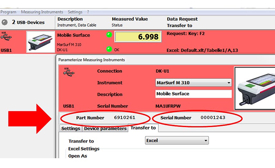
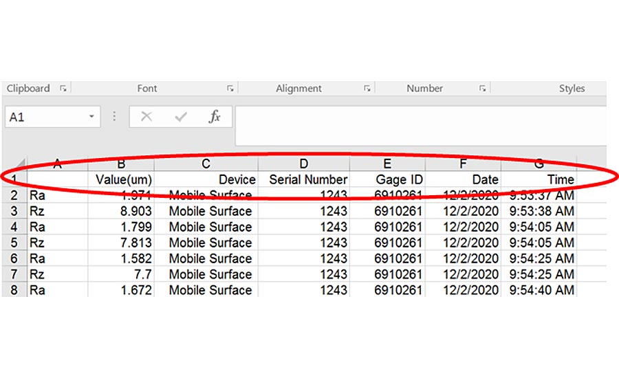
Figure 2: Data collection practices include the collection of all information about the measurements, not only the measured results and when they were measured, but also what instrument did the measuring. Source: Mahr
*Click the images for greater detail
One of the potential open loops in data collection and process monitoring is that while many types of measurement tools can collect data, information is not provided about what measuring device performed the actual measurement. There are very good gage control systems that track gages and ensure they are maintained and certified on a regular basis. And while they may be tied to a particular work cell or operation, there is no reflection in the collected data that the gage assigned to make the measurement was actually used to perform it.
When collecting surface finish measurements data, it is important to know that the measurement was made on the equipment that was dedicated to that purpose. Imagine if, in addition to the important measurement results and profile information, the gage also sent a unique gage identification number, the part number it is measuring, and a date and time stamp to the data collection system. With this, the measuring loop would be complete.
Often this can be easily implemented with complementary software that enables the user to add information concerning the unique gage identifier, part number and setup parameters for the measuring system. This enables a controlled and calibrated measuring instrument to be used with the parameters set up for that particular part.
Automating Surface Measurements
It is clear that a surface system used by a trained inspection technician may not perform as well in the hands of a machinist, nor may it be capable of keeping up with the rate that the machine is producing parts.
Because of this, standard bench or mobile surface systems may not be the best choice for specific inspection processes at the point of manufacture or for best throughput by the operator. Machinists are there to make parts; handling, measuring, and moving parts can reduce productivity. This becomes a target area where high-production facilities are looking to reduce the amount of operator interaction with the part.
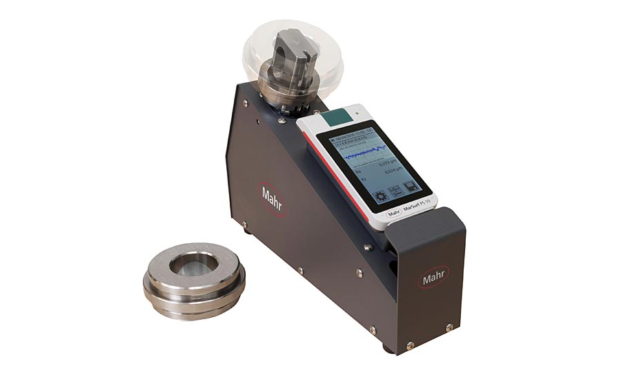
Figure 3: Custom fixturing for a portable surface gage helps automate and speed the measurement by eliminating time-consuming part positioning. Source: Mahr
To many production engineers, automation with custom gages means a large gaging station which parts are passed through. The automatic gaging station measures and sorts per the part’s required specification. While this is a true example of an automated gaging process, there are also many—and sometimes simple—changes that can automate the process. This is because automation provides an operational improvement to an apparatus, process, or system with mechanical or electronic devices that take the place of human labor. A small process change, an automated feature of a measuring system or a modification to a standard gage that can make the system easier to use, provides this operational improvement.
Thus, any time a customized gage replaces or even shortens operator involvement, some form of automation has been provided. Every time human involvement is reduced or replaced, the measuring process is apt to speed up and manufacturing costs are reduced.
Fully Automated Surface Gages
A new and smarter set of features are being added to surface gages for the specific purpose of allowing automation of the gage, thus enabling it to become part of in-process surface finish gaging improvement.
A fully automated surface measuring process is the ultimate custom gage solution. It takes the operator completely out of the picture and can run unassisted in a very reliable manner moving, manipulating and measuring the parts.
There are two levels of custom gage automation involving part movement within the gage. The surface measuring system can be designed for an automated process as a standalone station. Alternatively, the surface system can be a component of a dimensional gaging station where the part is presented to the surface gage for measurement, controlled by the PLC system running the whole gaging station.
Surface systems designed as standalone stations are often robot fed and may or may not include part manipulation/movement. Standalone stations have all the gaging components in place with the measuring system sending information back to a main PC running the surface system, changing probes and any movement of the axis to position the surface probes. This type of system has a customer program that knows the various parts to be measured and uses sensors to verify when a part is in place, when to take a measurement, and when to provide gaging results for disposal. These custom solutions are specifically tailored to the speed of the process, the part tolerances required, the environmental conditions of the process, and the capabilities of the system that is bringing the part to the gaging station.
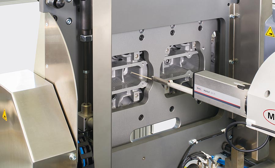
Figure 4: A fully automated surface inspection system takes complete control of the process—part positioning, probe selections and feature measurement. Source: Mahr
For a fully automated and versatile in-process system, another level of communication skill is required. A full serial system built into the surface gage using various commands is needed to take measuring steps from the PLC, which can begin the measuring process and parameter calculations. Then when the PLC is available, it will request the surface system to send those results back for storage and analysis.
With short part runs and flexible machining centers, it is not unheard of for systems to manufacture and measure a family of similar parts having slightly different characteristics and specifications. Therefore, the surface system must have the ability to take a new part program download from the PLC, and measure for the parameters and tolerances specified for that part.
Thus, these systems are truly designed with Industry 4.0 in mind. They would be networked and act as an intelligent source always online. They would work with the machining and part handling systems around them, knowing what part is coming along and its serial number. When measured, the part information would be sent off to the cloud for review virtually, anywhere in the world. Additionally, not only is the measured data available, the automatic gaging station can also provide information about its working status; perform and confirm automated calibration processes; and even offer online service/troubleshooting information if needed.
Semi-Automatic Surface Systems
Another level of automation brings movement into a separate surface gaging operation. Often parts have to be moved or manipulated to make the check required (e.g., the probe has to be inserted precisely into a bore or the part rotated to a number of different orientations). Requiring an operator to repeat these precise movements is difficult and time-consuming. Thus, with this type of system the user places the part into position and then the measuring station controller takes over, positioning the part precisely to the measuring probes.
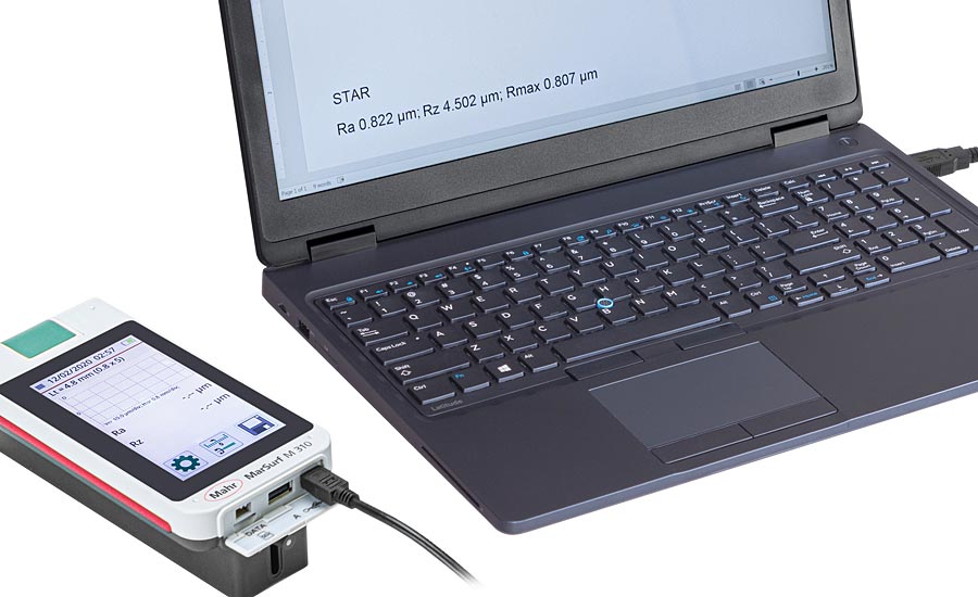
Figure 5: Many products allow for direct communication to a PC/PLC for full control—from loading part parameters to measurement control and data collection. Source: Mahr
When an off the shelf portable surface finish system is employed as part of an automated dimensional / surface station, the gage must have the communication tools needed to take commands from the PC or PLC running the gaging station to help automate the measuring cycle. Today many portable surface gages have two-way communication built into them. As with the data collection methods mentioned above, most are capable of receiving a signal via a switch to start a measurement and then send the results to a remote storage system.
Automating Manual Gages
If a manual gage is designed with the specific goal of making it easier to stage the part, then process automation has been accomplished. Similarly, if the manual gage is designed to make multiple checks: the gage is reducing or taking the place of human labor and again the goal is accomplished. More surface gages are being built into simple fixtures that aid the user in many ways. For example, parts may be too large to easily be brought to a surface gaging station or too small to precisely position to the surface probe. By creating relatively simple fixtures, probes can be precisely moved and locked into position for influence free surface checks.
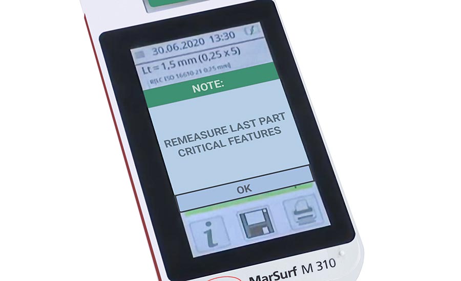
Figure 6: Measuring systems when implemented into remote control operations can act as mini-terminals—displaying comments to the user. Source: Mahr
With the powerful two-way communication tools being built into portable systems while the part measurements are being made, the data is recorded in the cloud so others at a remote factory can be monitoring the results (e.g., as a new process is being developed). They could be viewing the process live as each new part is being measured. With these new communication skills enabled, the surface gage itself can even act as a terminal—and communicate information back and forth. For example, as a part’s surface is on the edge of being too high, the remote user can send a message to the operator via the surface gage to say, “increase RPMs 10% and measure the next part.”
In summary, there are many ways that surface systems can be implemented in custom gage solutions to help automate the measuring process, whether by simple modification to a standard gage, or building a custom CNC surface measuring system. But they all have the same goals: speed the process, eliminate the influence of the operator, and generate better measuring results.
Opening Image Source: Mahr.
Looking for a reprint of this article?
From high-res PDFs to custom plaques, order your copy today!


