NDT | Back 2 Basics
Flaw Detection 101
Each NDT method has its advantages and disadvantages, so knowing what your flaws of interest are and where they tend to be located can be extremely helpful.

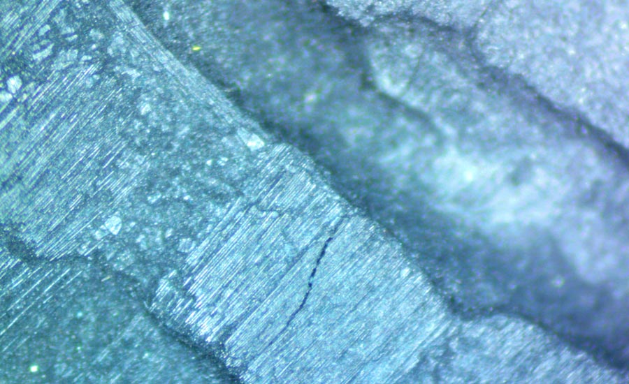
FPI Crack Zoomed. Image source: Weaver NDT
Flaw detection is the primary focus of all nondestructive testing (NDT) inspections. But before we dive into actual flaw detection, we need to have a solid understanding of what a flaw is. The term has been the subject of many discussions and debates within the NDT community for years. In fact, as recently as only a few years ago, you could find several different definitions of flaw, across many NDT procedures and specification glossaries. It was even defined differently within ASNT’s own NDT glossaries for various methods. The Ultrasonic glossary defined it as “an anomaly or unintended discontinuity” while the Visual glossary stated it was a “rejectable anomaly.” So, these inconsistent definitions have caused much confusion and have led many to use the terms indication, defect, and discontinuity as interchangeable words for the term flaw. But, in reality, this is not correct. The proper definition of a flaw is “an indication which is determined to be a discontinuity, but does not exceed rejection limits.” Once a flaw exceeds rejection limits, it becomes a defect.
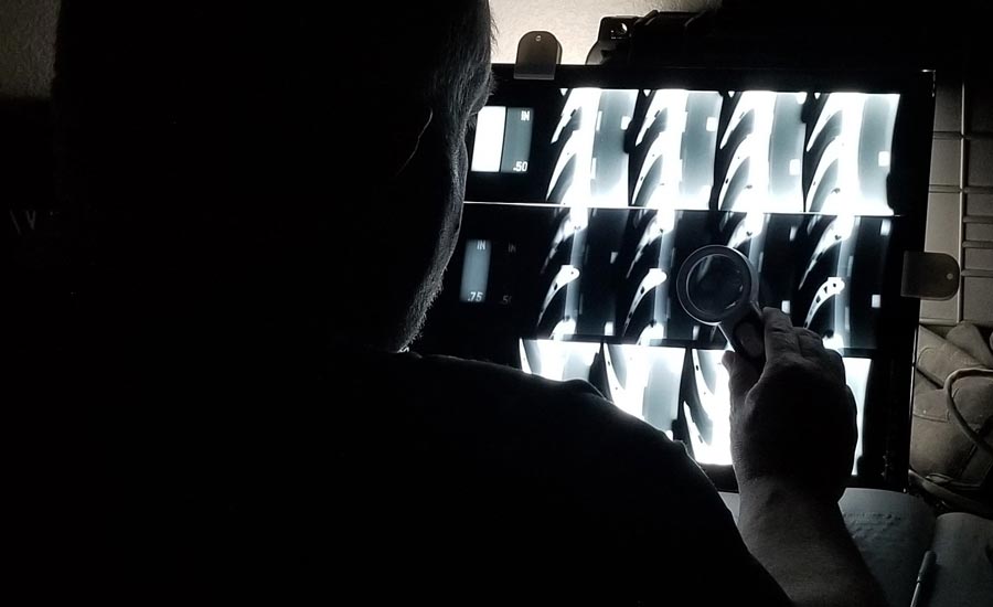
Viewing x-rays. Image source: Weaver NDT
Flaws are the targets of nearly all NDT inspections. They can be found in every type of material and component, no matter the method of manufacturing, processing, or finishing used. They can also develop due to service use and this creates a new secondary detection that must be performed at specific intervals. All of this means that selecting the proper detection method is crucial. Because, even if a flaw is not actually a defect, you still want to be able to detect and evaluate them.
Flaws are typically categorized into four groups:
-
Inherent - originating during the raw material process, such as a casting process.
Includes: shrinkage, cold shut, porosity, cracks, inclusions, and segregation -
Primary Processing - developing from material forming, like forging and rolling processes.
Includes: laminations, stringers, seams, laps, gouging, and cracks -
Secondary Processing - induced by material finishing, operations like grinding and machining.
Includes: tears and cracks caused by grinding, pickling, and heat treatment(s) -
Service - originating due to service conditions, like cyclic loading or environmental situations.
Includes: corrosion, stretch, and cracks caused by fatigue, creep, and hydrogen embrittlement
Visual crack Image source: Weaver NDT
These four groups have different types of flaws associated with them. There are other flaws beyond those listed. However, a crack could occur during any one of the groups, but the root cause of a crack would develop from many different forms of failure mechanisms.
Flaws also come in many different sizes, orientations, and shapes and they can even be small material differences that are hard to identify. Because of all these variations, detection of flaws may be difficult, and it can require a combination of several inspections to provide full part coverage. The inspection method selection will have a huge impact on the success of an evaluation’s sensitivity and detectability.
Each NDT method has its advantages and disadvantages, so knowing what your flaws of interest are and where they tend to be located can be extremely helpful. To help with this, there are a few easy ways to select the appropriate method for your specific flaw detection need. The most basic thing is the location of the flaws, are they internal or external? If they are one or the other, you can eliminate about half of all the methods.
For external flaws, the most common and widely used method of detection is visual testing (VT). If you have good access to the entire area of focus, then it is possible that the only inspection you may need is visual. Usually though, for critical parts, visual inspections will need to be accompanied by an additional external inspection that is either a visual aided inspection like liquid penetrant testing (PT) or magnetic particle testing (MT) or by a probing method like electromagnetic testing (ET) and surface ultrasonic testing (UT). This is especially true when tight surface flaws are the targets of the inspection.
Magnified Visual Shape Defect Image source: Weaver NDT
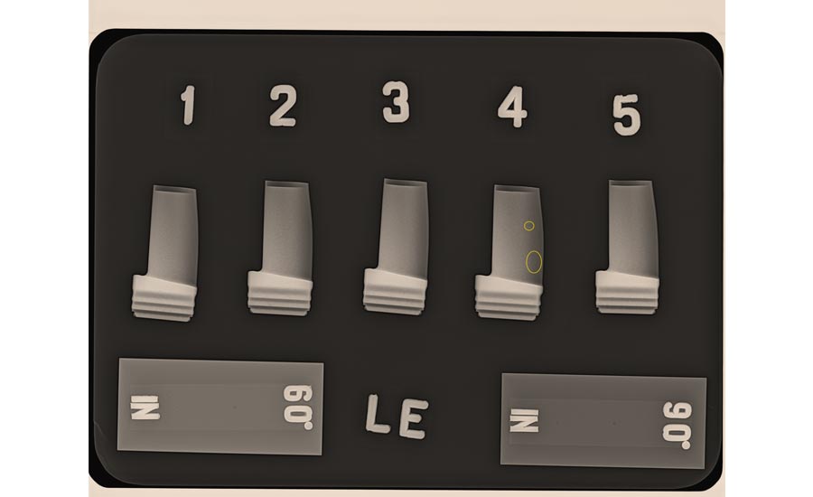
For internal flaws, the most common method is radiographic testing (RT). Radiography is especially useful when the subjects have complex geometry. In many cases, the internal design will make RT the only option when flaw detection and visual images are required. If images and location of defect is not required, then resonance inspection (RI) is another possible internal detection method. Gaining access to all inspection areas of a part can be difficult the more complex a part design is, but for many parts where this access is possible, alternate internal methods like ultrasonic testing (UT) and phased array ultrasonic testing (PAUT) can be used.
After the internal and external methods are selected, the next key thing to consider is method optimization. As an example, we consider both radiographic testing (RT) and liquid penetrant (PT). For RT, the density and geometry of the component will play a large role in optimizing the RT to ensure that the best flaw detection is possible. The three main items of optimization are: 1) X-ray tube power, enough to provide proper penetration of the subject part. 2) X-ray film, image plate, or detector sensitivity, high enough to provide the required sensitivity. 3) Inspectors need to be properly trained, qualified, and certified.
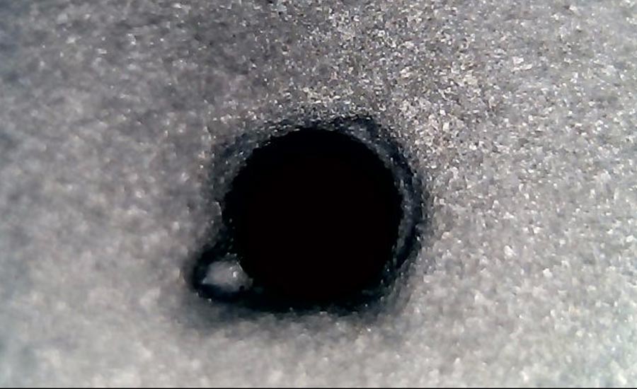
X-ray porosity Image source: Weaver NDT
For PT, the main items are: 1) penetrant type, method, and sensitivity level 2) developer type 3) proper timing of all the critical processing steps. 4) Inspectors need to be properly trained, qualified, and certified. Any method that is selected will have some aspects that need to be considered, evaluated, and experimented with, to ensure the best chance of flaw detection.
The last, and certainly not the least, piece of any flaw detection program is proper personnel training, qualification, and certification. All the best tools in the world need to have the right people operating them. Every company that is responsible for inspections should have what is called a written practice. This document should lay out all the requirements for formal training, experience, qualification, certification, and recertification for all NDT methods. There are guides and standards that these documents should be written from that when done properly should help ensure that your inspectors can consistently detect flaws of interest.
To review, a flaw is “an indication which is determined to be a discontinuity, but does not exceed rejection limits.” Successful detection of flaws has several main components, proper NDT method selection, optimization of the methods selected, and properly trained and certified inspectors performing the inspections. If all of these are done properly, your flaws of interest should be detected.
Looking for a reprint of this article?
From high-res PDFs to custom plaques, order your copy today!


