Quality 101
The Next Dimension of Precision: Integrating Rotary Tables into Coordinate Measuring Systems
The accuracy and reliability of CMMs and PCMMs are foundational to quality.
All Images Source: Wyvern Industrial Technology, LLC
Coordinate measuring machines (CMMs) and portable coordinate measuring machines (PCMMs) are indispensable tools in the realm of dimensional metrology. Typically, these systems operate on three or seven axes, respectively, allowing for the measurement of an object’s physical geometrical characteristics in three-dimensional space. However, the integration of rotary tables as an additional axis—effectively the fourth (and potentially fifth) for CMMs and the eighth for PCMMs—has emerged as a game-changer, offering significant benefits in performance. This article explores the transformative impact of incorporating rotary stages into coordinate measuring systems, enhancing their capabilities and the efficiency of the measurement process.
What Is A Coordinate Measuring System?
A coordinate measuring system, whether a CMM or a PCMM, measures the geometry of physical objects by sensing discrete points on their surfaces with a probe, and in some cases using an additional sensor for 3D measurement. These systems can be manually controlled or operate via computer control, with measurements taken along the X, Y, and Z axes. The accuracy and reliability of CMMs and PCMMs are foundational to quality control in manufacturing and engineering.
What Is An Additional Axis?
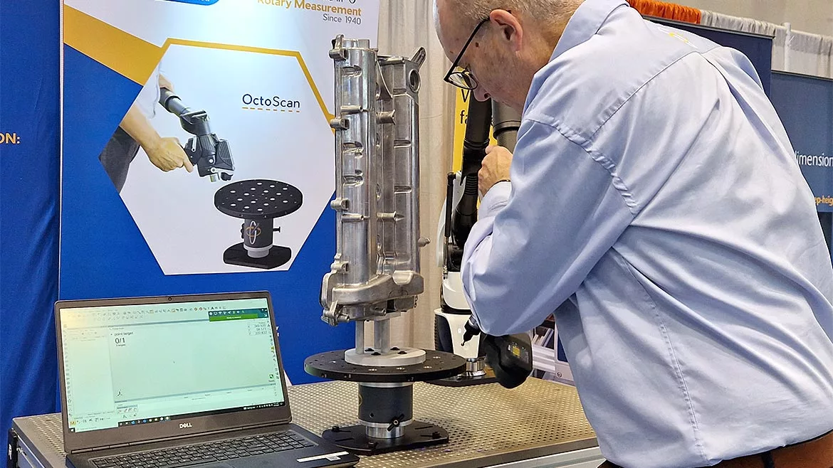
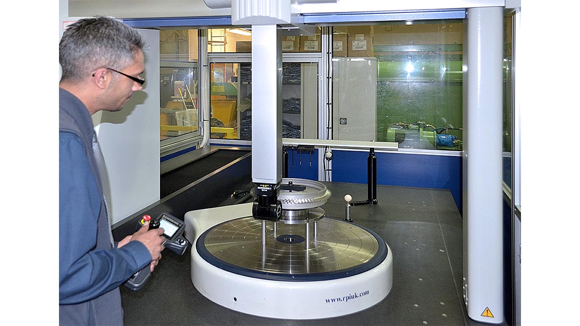
An additional axis in the context of CMMs and PCMMs refers to the integration of a rotary table or rotary stage. This axis is a manual or motorized platform that rotates the object being measured, allowing the measuring probe to access various points without the need to manually reposition the object or measuring device. For CMMs, this is often the fourth axis, while for PCMMs, it can be the eighth axis, enhancing the system’s ability to navigate and measure complex geometries.
Why It Is Useful
The utility of an additional rotary axis is multifaceted. For PCMMs, it significantly expands the measuring volume and facilitates the inspection of larger and more complex objects by providing additional angles of approach. Typically, to otherwise measure large objects can involve moving the measurement device around the part, or moving the part into more advantageous positions. Not only does this slow down a measurement, but can also introduce increased uncertainty in measurement values.
CMMs benefit from easier part access, streamlined programming, and a reduction in probe changes, which collectively optimize the measuring process. The rotary table’s precise control and movement can improve inspection time and potentially increase the accuracy and repeatability of measurements.
Considerations When Specifying The Additional Axis
When integrating a rotary table into a coordinate measuring system, several key factors must be considered to ensure that the additional axis enhances the system’s performance without compromising the integrity of the measurements:
1. Table Size: There are several considerations when determining the correct size of table to select for a CMM. Not only does the table have to physically fit on the CMM (and thus is dictated by the size of the CMM bed), but the parts being measured also have a bearing. Not only do the parts (and associated tooling) need to fit onto the table, but the mass of theportable overall load also needs to be considered. A rotary table will have a maximum payload specification which is usually included in the product datasheet. However, if that load is spread unevenly or unusually, this could have an impact on the drive performance. If this is the case, it is advisable to seek advice before specifying a unit.
Specifying table size for a PCMM is comparatively much simpler. In most cases, PCMMs are used with manually controlled precision rotary stages, so the performance of drive components is not a consideration. However, access, future-proofing and portability are all considerations. A larger tabletop size may offer greater capacity for large parts, but could also be less practical to move around the shop floor. Some systems offer interchangeable tabletops meaning that you can switch between large and small tops depending upon your application.
2. Accuracy and Repeatability: The additional axis should have high accuracy and repeatability specifications that align with the measuring system’s capabilities and the tolerances of the parts being inspected. Typically, precision rotary table manufacturers will report rotational performance data in arc seconds (an arc second being ~0.0003 deg). However, CMM manufacturers will specify accuracy and repeatability of their devices as a dimensional value. The consequence of this difference (which is a result of the differing nature of how performance is quantified in different types of motion) means that performance is also dictated by a size of the part being measured. For example, a very tall part might see a disproportionate effect of the “coning” effect of a table in results compared to a smaller part. The consequence is that consideration of performance should be given to each specific application. Again, in the case of any doubt, it is wise to seek advice on this matter. Notwithstanding, a typical precision table will usually have a negligible effect on the performance of a CMM. Indeed, any uncertainty introduced is normally more than counteracted by the benefits and improvements introduced by the reduction in movement of the X, Y and Z axes.
In the case of a PCMM table, these considerations are somewhat reduced, especially in the case of a 3D scanning application. However, geometric performance of the axis is still an important consideration. Additionally, the accuracy of the method of determining position can also have an impact. This typically means either the accuracy of the encoded axis, or the accuracy of the indexing positions of the tabletop.
3. Table capabilities: There are a number of other considerations in selecting a table that are also important to be mindful of, depending upon the application.
The configuration of the table in terms of drive system is a consideration, particularly in applications which require high accuracy or there is a high payload. Certain motor types can introduce a phenomenon referred to as “backlash” after moving into position. This results in the table shifting slightly in position as it stops in place, which can potentially cause minor positioning considerations which may impact some applications. In addition to this, consideration should be given to the type of bearing selected for the drive system. Whilst air bearings are considered extremely high accuracy, they typically are less suited to high payloads, and can be considerably more expensive than alternatives.
Features of a table are also something that should be taken into account when determining the most appropriate option. Some tables offer an air flotation mode which allows easy repositioning of a table on the work surface of the CMM. This can be particularly useful if additional space is needed when the rotary table is not required. Some other tables also offer multi-orientation positioning, and even multi axis rotation. Depending on the complexity of a part, these options can offer considerable benefits in ease of use and performance.
How It Is Achieved
Integration of a rotary table into a coordinate measuring system requires changes from both a hardware and software perspective.
In the case of a CMM, in addition to selecting a table configuration that suits the CMM design and parts that will be measured, the CMM must also be capable of accepting signals from a fourth axis through its controller. Whilst many CMMs in the field have this capability even when it is not in use, this is not universal. If this is the case, the controller may be upgradeable by the CMM OEM or a third party service company. Alternatively, some precision rotary table manufacturers are also able to supply a standalone 4th axis control unit that performs this task.
The software used on the CMM will usually also need some alterations to accept 4th axis control. This may mean upgrading the software or unlocking this function in order to access the capability. As with hardware control, the CMM OEM or third party can give advice on the most effective way to implement this.
Once the capability is added, it is also advisable to ensure that any operators and programmers receive suitable training on the new capability. As with the implementation, most CMM service providers are able to assist with this.
PCMM integration is typically somewhat easier. In the case of indexing tables, after hardware selection, the predominant setup steps involve software use. The table will be provided with a calibrated point map that serves as a coordinate system. This is used in the 3D software used by the measuring arm to determine the relative position of the table. This is input into the software to ensure that individual measurements and scans are correctly aligned by the software. Beyond this, simple measurement process changes are required within the measuring routine and no further setup should be required.
Conclusion
The integration of rotary tables as an additional axis in coordinate measuring systems marks a significant advancement in the field of metrology. This addition opens up new possibilities for manufacturers and engineers to achieve higher precision and efficiency in their measurement processes. As the demand for more complex and precise measurements grows, the adoption of rotary stages is set to become a pivotal feature in the evolution of coordinate measuring technology, ensuring that quality and precision remain at the heart of the manufacturing process.
Looking for a reprint of this article?
From high-res PDFs to custom plaques, order your copy today!


