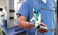
So you’ve designed a high performance bearing or friction-free coupling, and the first thing you are asked is: What is its actual restraining torque? You’ve done your best to make something unmeasurable, and now you’re being asked to measure it.
As with watch springs or subminiature electronics trim controls, these very small torque forces can be very important. They can always be measured with the right instrumentation, but repeated measurement for design verification or for quality control can be very time-consuming, and many devices for measurement are not suitable. There is a wide range of digital torque testing equipment available, including computerized and semi-automated systems. Some of these are in use on production lines for measuring anything from bottle capping processes to machine parts. But whilst torque sensors are available for precision work down to just a mN.m, fully computer-controlled systems to make the most of them are not always an affordable option.
Where all the forces involved are light, these conspire to make all aspects of testing relatively significant. If, for example, we were to test the torque required to rotate a heavy axle in an oil-lubricated steel bearing, the breakaway torque would be small compared with the inertial torque, which would be greater than the subsequent running torque. Here, additional forces through minor misalignment are likely to be disproportionately small. In the case of a fine polymer or ceramic bearing, however, under light loads, the three torque elements are likely to be very similar as well as being very small. Additional forces through misalignment are likely to be proportionately significant.
Components of precision
Manufacturers of testing systems are presented with a considerable array of products that their customers need to test for torque, but not many are circular or even symmetrical. An accurate test requires location of the axis of rotation and presenting this consistently within the axis of the test system. This involves selection of the best gripping fixtures to avoid introducing extraneous forces, often requiring the design and manufacture of custom grips. A torsion spring, for example, will need to be mounted on a spindle matching its inner diameter, yet without undue tightening within its intended test rotation. If not, deflection during test may change the symmetry and hence the measured torque.
Each specimen to be tested must be gripped in an identical and precise way, otherwise a difference in alignment between specimens can appear to indicate imprecision in the product being tested. Similarly, a specimen with an inherent defect may have this masked by a misalignment during testing.
It is important to recognize that alignment needs to be precise in two planes: concentric and perpendicular, so flexibility between fixturing points must be written out. A very flat bearing may be easier to fixture, for example, by designing a custom socket grip, whereas products with length such as rotating sleeved inserts, or syringe fittings at the end of a plastic tube require careful support along their length so that concentricity set in the fixture end is maintained at the point of applied torque.
A light grip?
It may seem intuitive to hold very light, precision components in a very light way, allowing for freedom of movement during rotation. If the rotating parts in actual use drift around the axis slightly, and this does not matter, then why should it affect the test? The correct answer is that a ‘test to the best’ will isolate and reveal noise that is solely in the rotation and not due to lateral movement. A perfect component rotating in a perfect system will of course show a smooth cycling pattern due to imprecise alignment, that can be ignored—but perfect systems don’t exist.
The alternative is to grip the rotating parts very precisely and rotate them perfectly concentrically. This will show up any unevenness in the rotation due to manufacturing imperfections or subsequent wear or damage. Custom fixtures may have to be designed to suit each product to be tested, fitting them exactly and eliminating lateral movement or flexure. The control and analysis software can therefore present a complete profile for the rotating parts where cyclic features and noise are solely evidence of unevenness in moving surfaces from manufacture, wear or damage.
It may seem obvious that the measurement of running torque requires precision, but the same is true of static torque or of breakaway torque. In the latter, sometimes referred to as inertial torque or starting torque, any additional lateral slip will obscure the picture, especially in the finest bearings or rotary controls. Here the torque required to initiate rotation concentrically may be very similar to friction due to initiating lateral slip.
The ups and downs of torque testing
A number of common torque tests, such as caps, closures or couplings, involve screw threads, where friction between engaged surfaces varies by the number of applied rotations, accuracy of pitch, tolerance within the thread depth, and by pressure applied. That’s a lot of variables to control in a test system. How should the torque head of a testing system move axially in response?
Cork testing systems have been designed for profiling the forces experienced in extraction of sparkling wine stoppers. Without a thread, these machines are geared in a fixed ratio to pull and twist simultaneously. Actual consumers may have different manual techniques, but this gives consistency and repeatability to the cork removal test. With a threaded closure, should the axial pressure (on an increasing or decreasing count of threads) be consistent, proportionally changing, or cancelled out? With friction naturally in the action of closing and opening, a completely floating torque sensor is both hard to achieve and not realistic. But then if you watch how people actually handle screw caps, you will see a lot of variation. It is better to apply a consistent test with known variables, which is repeatable and accurate. You can then determine the values that correlate with a good seal that can also be easily opened.
In designing its precision torque tester, one major systems designer included a counterbalance mechanism to cancel the effect of the mass of the moving crosshead, torque sensor and fixture acting on the specimen under test. The last thing you want during testing is the weight of the test machine preventing your threaded specimen from untightening properly. In contrast, other tests actually demand a mass to be applied whilst the specimen is turned—exactly what we all do when pushing down and twisting to open child-resistant medicine bottles. A specific mass can then be added to the crosshead to apply a known axial force as torque is applied through the lower fixture. In this way the test becomes appropriate, specific and repeatable.
Testing machine concentricity
At the heart of fine torque testing is the precision within the test axis. Precision-made fixturing is essential, but so is the ability to align and adjust the concentricity of the system itself. Changing a torque cell or applying a different fixture will change the configuration, so it is essential that the torque drive spindle and the torque cell axis can be quickly and easily realigned without the need of further instrumentation or particular expertise.
Summary
Where torque forces to be measured, or variations in them, are very small, precision at every point in the testing system is essential. Custom fixturing may be indicated, the right sensitivity of torque sensor goes without saying, but the ability to adjust the test system itself for perfect alignment is fundamental. When these all come together with controlled axial force, you have a precision torque tester for measuring what you might have considered unmeasurable.


