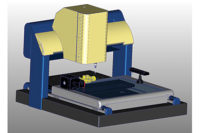
There’s nothing quite as exciting as diving for the E-Stop button when your computer numerical control (CNC) measuring system takes off at high speed in the wrong direction. If you’re lucky, you catch it before something dramatic happens. If not, well maybe nobody saw that.
After the heart rate returns to normal, the next question is: How did the alignment get screwed up?
Alignments: A Fundamental Concept
In the late ‘70s the costs of computing dropped to a point where computations that were previously only possible on mainframe computers suddenly were feasible on devices like mini-computers and programmable calculators. At the same time, automatic sensors, both contact (touch probe) and noncontact (video cameras) became available at a reasonable cost. The trend accelerated with the advent of the PC and the era of computer aided inspection was born. By the mid ‘80s, virtually every measuring system manufacturer was offering measurement software for both manual and CNC controlled 3-D measurement systems. Multisensor measuring systems that combined several sensors on one system with calibrated offsets between them allowed complex application problems to be solved with full automation.
The software used to create and execute these automated inspection routines varied widely from one manufacturer to the next in terms of overall functionality and user interface paradigms.
There was, however, one concept common to all measurement software: the concept of alignment. Unless the user was willing to commit to placing the part to be inspected in exactly the same location on the machine every time, there had to be some way to program the inspection motion relative to the part rather than from the machine’s home position (the point at which all scales read zero). Furthermore, the location of a feature, such as a hole, is dimensioned from a reference point on the part. It is meaningless to report feature locations in machine coordinates. Thus, alignments fulfill two important needs in automated inspection: they allowed both motion programming and feature reporting to be done relative to the part, not to the machine.
One would think that such a fundamental function would be easily learned and applied, but it continues to be a source of frustration for users of many types of measurement systems. Alignments don’t always end up as expected; they sometimes flip arbitrarily for no apparent reason, or require the person creating the measurement routine to find some way to trick the software into creating the desired alignment.
Why is alignment so hard to understand?
There are several reasons why alignments are difficult to understand.
The first is that there is no tangible result from the alignment function. When a machine move is programmed, the machine moves. The programmer can immediately see the result of the command. When a feature is measured, results are created. The programmer can immediately see the result of the measurement. But the alignment creates no motion or result. Experienced users check the Digital Read Out (DRO) to verify the alignment; they drive the sensor to a position near the desired Zero Point, check the numbers, then move the sensor in what they expect will be the plus X direction and check that the DRO X value goes positive (and the Y and Z don’t change), and then move the sensor up and check that the DRO Z value goes positive, etc. But less experienced users who rely on the software to operate as they expect are often surprised.
A New Standard for Alignments
The second reason is that for more than 20 years there were no rules defining how measured features should be combined to create alignments. Each measurement software’s developers created their own rule bases for the alignment function. Finally, in 1994, Section 4 of the ASME Y14.5.1 standard included a rule base in tables 4-2, 4-3 and 4-4 to define the creation of Datum Reference Frames (DRF). For consistency, measurement software should use these rules for creating alignments, though not all measuring systems follow these standards completely.
In addition, in some cases, the user is required to construct a feature from other measurements before creating the alignment. A good example would be an alignment based on a plane and two circles. Many systems require the user to construct a line from the two circles and then reference the constructed line in the alignment function. For a newer user, this requirement is not obvious until an attempt to create the desired alignment fails. The tables in Y14.5.1M 1994 state that the direction of the X axis shall be from the center of the first circle to the center of the second circle. Most measurement software implements this rule exactly, though again, some software may not.
Early Attempts: Before Software
Early manual systems such as optical comparators and manual CMMs relied on tooling mechanisms to physically align the part. Rotating screen bezels, leveling jacks and push-pull alignment knobs were used in various combinations to adjust the relationship between the machine and the part. The Digital Readout (DRO) included zero buttons to set the scale value to zero. Early software attempted to mimic this methodology with software leveling, zeroing and skew adjustment functions. These functions put the burden on the user to create a valid, complete sequence of steps that would result in the desired alignment.
Alignments Flip for No Apparent Reason
Why do alignments flip? Other than software bugs or operator error, the most common reason alignments flip for no apparent reason is that a manual alignment feature has been measured in the opposite direction from the direction in which it was originally measured. For example, during the creation of the routine, the front edge of the part is measured left-to-right to define the positive direction of the X axis. But the next time the routine is run, the user measures right-to-left, causing the alignment to flip. Modern software is designed to account for differences in measurement direction, avoiding the alignment flip that torments users and crashes sensors, usually at the worst possible moment, and unfortunately, in the most expensive way.
Improving the Alignment Experience
It can be seen that the current alignment paradigms have created a frustrating trial and error experience. This can be traced to the lack of feedback as the user creates the alignment, and the proliferation of commands required to create an alignment.
Thinking back to the means by which experienced users check an alignment, the issue really comes down to two questions: Where is the zero point (origin) of the alignment and which way do the axes point? Modern 3-D measurement software has the capability to make the answers to these questions blatantly obvious using real-time, on-screen animations. Additionally, the Y14.5.1 rule base makes it possible to reduce the alignment experience to a single command.
In the most recent implementations, as the user adds a feature to be used as part of the alignment, an alignment is computed based on the rules contained in Y14.5.1 Sec 4. This allows all combinations to be handled with a single command. To display the results of this action, a color coded trihedron is drawn at the origin of the resulting alignment with the arrows showing the direction of the axes. Animation is used to show the user if the alignment is fully defined or not. A “fully defined” alignment is one where all six degrees of freedom have been constrained or locked down. This animation helps guide the user in selecting the remaining alignment features. For example, if the trihedron is shifting back and forth in the X direction, it makes no sense to add a feature that is parallel to the X axis because it will not add any additional constraint to the alignment.
Controls for selecting which axis is defined by each alignment feature allow the user to set both the axis and direction in whatever combination is desired. Again, the animated trihedron arrows show the user what will happen.
It is important to note that the user no longer has to know anything about direction vectors or pre-constructions. All they need to do is select the features and adjust the directions, if necessary. When the trihedron shows the desired alignment, the user saves that step.
Can-May-Must: The Order Matters
With this graphical feedback, troublesome problems like improper alignment feature order become much easier to understand and can be easily avoided. In the following example an alignment is based on a plane, a circle and a line. But the order in which the features are used is important, since the Can-May-Must Rule (Rule of Maximum Utilization) (Y14.5M 2009 §4.10 p.58) comes into play. (For more on this see Bill Tandler’s excellent discussion in Quality August 2012).
Let’s see how the Y14.5.1 rule base and good user feedback can help the user avoid a mistake.
In the first case, the user selects the plane, then the line, then the circle. After each selection, the trihedron moves to show the user where the origin is located. After the three features have been selected, the user sees that the origin is located at the front edge of the part, not at the center of the circle (Figure 1). This is as it should be. According to Y14.5 - 2009, the Y origin was not yet defined when the line was selected. The Can-May-Must Rule says that if the line can set the origin (it Can) then it Must.
The user sees that the origin will not be as expected and clears the secondary and tertiary alignment features and selects the circle, then the line. Now the trihedron is located at the center of the circle (Figure 2). The user has avoided a potentially disastrous mistake. An automatic move with the incorrect alignment could have caused a spectacular collision! At a minimum, the probes would have needed to be recalibrated, or maybe even replaced.
Even the cautious user pays a price in terms of productivity if there is no graphical feedback. The sensor is moved to the center of the circle and the user sees that the Y coordinate is not zero. The sensor is used to hunt for the Y Origin. Hopefully the user will realize the source of the problem and go back and edit the alignment step.
No Need for Constructions
Another advantage of using the Y14.5.1 rule base is the elimination of the need for pre-constructions. In the next example, an alignment is based on a plane and two circles. The user selects the plane, then the first circle, then the second circle. After each selection, the trihedron moves to show the user where the origin is located (Figure 3). Additionally, the X axis points from the center of the first circle through the center of the second circle, exactly as defined in Y14.5.1 Table 4-4 p.19. There is still the effect of the Can-May-Must rule. The first circle selected will define the X and Y origin, but the user can see the location of the origin and correct the order if necessary.
A Little Less Excitement
By creating an alignment experience that is graphical, repeatable and predictable, it is possible to simplify one of the most complex and important aspects of 3-D CNC measurement. In addition to improving the efficiency of part programming, the improved alignment experience has taken much of the (negative) excitement out of the task of creating and running CNC inspection routines.
This is a move in the right direction for the metrology user experience. Sensor, machine and part damage are avoided, and users will breathe a lot easier if the machine always makes a move in the right direction
|
TECH TIPS
|


