How deep does the rabbit hole go? Don’t ask Alice—consult a depth gage! Whether a hole is three microns deep or three meters, there are a variety of simple measuring options readily available. This article will attempt to educate the reader on what is available. The options are sorted by the readout style.
Micrometer
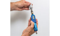
Micrometer style depth gages are a simple machine. They mate a micrometer head to a flat measuring base. The base is set against the reference plane or feature. The spindle passes through this base and on down to the feature in question. This type of gage may use electronic, mechanical digital, and Vernier measuring heads.
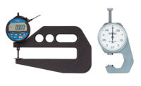
TECH TIPSDial indicator depth gages are comprised of a very standard length measuring gage mated to a flat base. As with the dial indicator type, depth bases are available to augment the depth measuring ability of a standard caliper. Superficial gages are intended to check smaller changes in depth. |
For depths between 0 and 1”/25mm, the gage may be set against a flat plane, such as a gage block or granite plate. Beyond 1”/25mm these gages normally require the anvil to be swapped out with one of a different length. Longer spindles cannot retract to the same plane as the base, and therefore the gage requires presetting with a reference master, such as a gage block.
Dial Indicator
Dial indicator depth gages are also comprised of a very standard length measuring gage mated to a flat base. Mechanical and electronic types are common. These may be more convenient than micrometer depth gages for several reasons.
The spring force exerted by a dial indicator makes measurements quick and very accurate. The increase in speed comes from the loss of a barrel which needs to be turned. The actuation and measuring force are provided by a spring instead. These gages may obtain more repeatable results from one operator to the next because of this reduction of user input.
Another feature of this type of gage is that the extensions thread in to the end of the indicator spindle. This allows quick range changes to be made. It also allows for the use of alternate contact points. Features inaccessible to a micrometer spindle can be measured using contact points with small outside diameters, disc, blade, needle, roller, 90° attachment, etc. The list of possibilities is long and includes many height gage accessories, which often share a common thread standard with a dial indicator depth gage, M2.5 and 4-48 being the most common.
On the topic of adaptation, a standard dial indicator may be converted to depth gage use with the purchase of a depth base. This simple attachment clamps to the stem of a standard dial indicator.
Modified Caliper Depth Gage
As with the dial indicator type, depth bases are available to augment the depth measuring ability of a standard caliper. For dedicated use, or oddly shaped application, many purpose-built caliper depth gages are available. Any of these styles can be found with digital, dial, or Vernier readout reading styles.
A novel feature available to this type of gage is the over/under contact point. This is similar to a standard caliper jaw in that it has 2 opposing anvil faces which share the same plane. This allows a user to measure irregular features such as a ring groove width without complex readings or extra math.
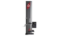
Depth capacity is another category in which this type of gage excels. Long electronic scales can be used to create depth gages with several meters of range. Large electronic scale depth gages typically have interchangeable depth bases and contact points to make the large investment more versatile. As with the dial indicator depth gages, these are typically made so they accept indicator contact points and/or height gage probes.
Superficial Depth Gages
This is a broader category that is lumped together due to similar intended use. Superficial gages are intended to check smaller changes in depth. In general, these are imperfections in an otherwise flat surface. These discontinuities may be designed or the result of damage.
Ripple Gage: Another modification on the dial indicator depth gage. This is suspended from a horizontal scale in order to display X axis and Z axis readings across a sample surface.
Surface Flatness:Many variations on this theme exist. Lever (test) indicators and linear (dial) indicators are used in the design. The concept is based on having a large flat reference base, which will skate across and span any imperfections. This base is then fitted with an indicator with a very fine point. This point is able to penetrate imperfections or damage to the surface to quantify the variation. One common use is to check the condition of a granite surface plate.
Chamfer Gage: This gage does not actually check depth. It checks the diameter of a chamfer or countersink on a bore. I include this gage here because of the similarity in design to a dial indicator depth gage. The measurement is taken by measuring the distance a cone of known dimensions is able to pass into the feature. A simple linear conversion factor is applied within the electronics of the indicator to convert this distance to the corresponding diameter.
Rivet Height Gage: This is similar to a dial depth gage, but it measures short distances in the reverse direction. As the name suggests, it was intended to check the height of protruding rivets from the surface being riveted. The outer shell of an airplane is a good example.


