Get to Know the Height Gage
The accuracy gets a boost when height gages with repeatable measuring force are introduced.
Height gages are a common sight in the quality department. Source: Fowler
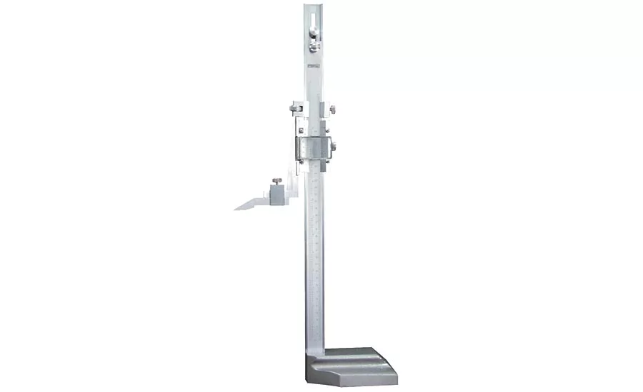
This is a height gage in a very basic form. Source: Fowler
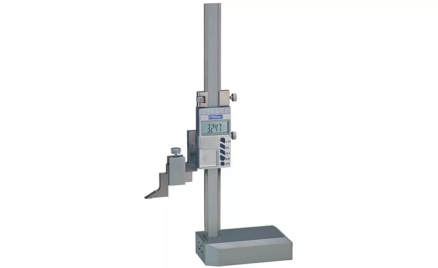
The readings from such a gage were simplified with the addition of a rack and pinion system which drives a spring-wound dial. Source: Fowler
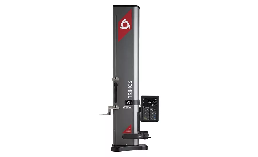
The digital age brought us digital gage readouts such as this example. Source: Fowler
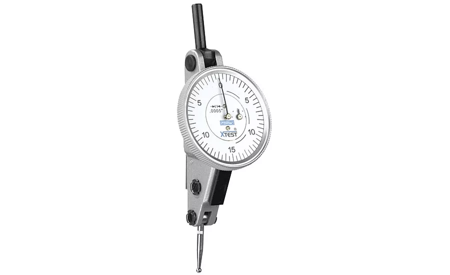
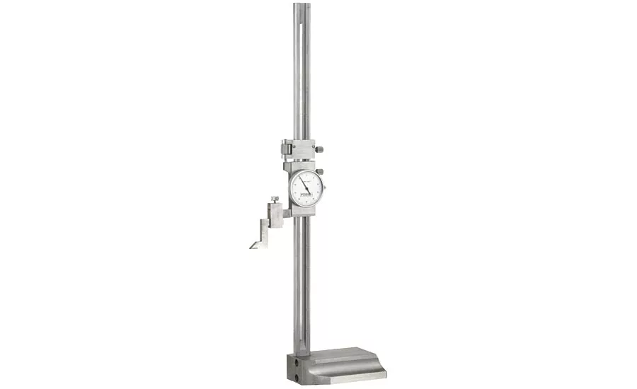
The accuracy of the gages can be improved with the addition of a dial test indicator. Source: Fowler
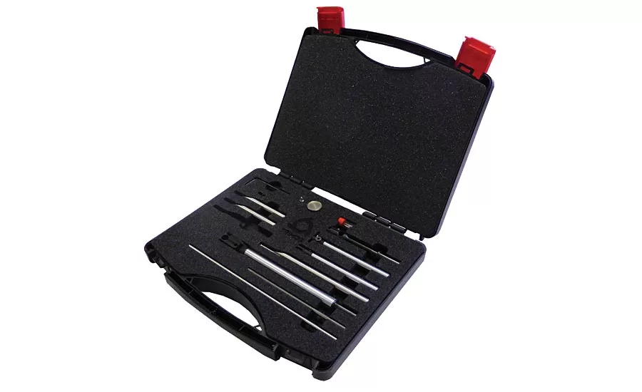
Since the flex in the measuring probe can be ignored, we are now free to have a plethora of probe attachments with different diameters, lengths, and angles. Many odd or deeply buried features are now measurable. Source: Fowler
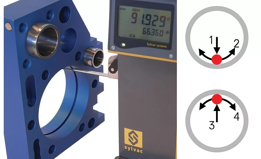
The next step in this progression is the ability to measure diameters. Source: Fowler

By measuring a series of holes, then rotating the part a known angle, and re-measuring these features in the same order, an X-Y map of their positions can be built. This can be used to check angles, off-axis distances, and even bolt circle diameters relative to the center point of the measured features. Source: Fowler
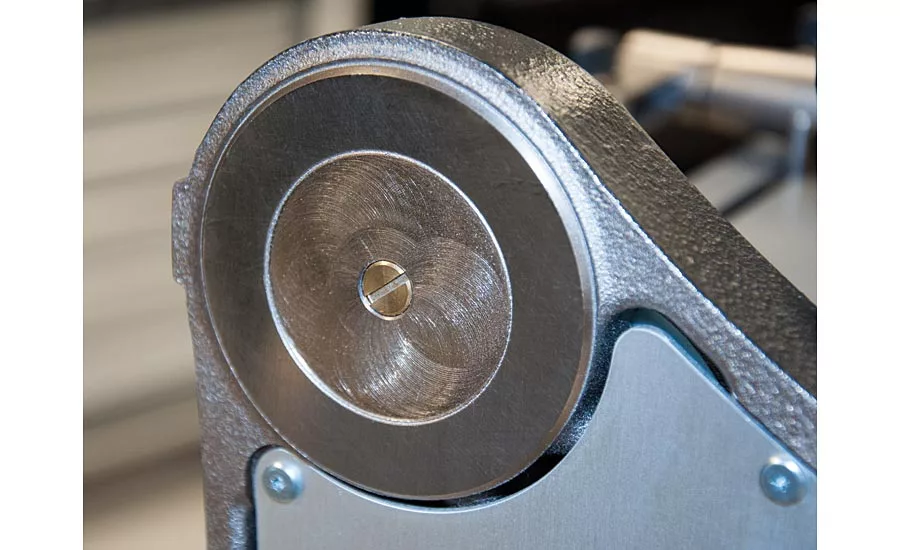
This has a supply system designed to depressurize if any one foot reaches the edge of the surface plate. This would help to prevent a height gage from coasting off the edge of a plate. Source: Fowler
Height gages have achieved a nearly universal presence in the quality control world. It is rare to see a QC department without at least one or two of these instruments. This commonality makes it easy to overlook just how accurate and flexible these devices are. They measure much more than the term “height gage” would imply.
In order to illustrate the full capability of modern height gages, here are examples of height gage technology from the simplest to the most advanced.
A height gage in a very basic form is not much more than a vertical caliper. They can be outfitted with a lens to make a reading of the Vernier scale easier on the eyes. A gage such as this can resolve down to about 0.001 inch. The Vernier scale itself is an advancement that is only about 500 years old. Simple linear scales are known to be at least 2,000 old.
The readings from such a gage were simplified with the addition of a rack and pinion system which drives a spring-wound dial.
Gages can also be a vertical version of dial caliper technology. The readings are much easier to take, but the resolution remains in the neighborhood of .001 inch.
The accuracy of these gages can be improved with the addition of a dial test indicator. This gains the benefit of resolution down to .0001 inch. The negative side is that the gage is reduced to being a repeating device. This increased accuracy is only effective within the range of the test indicator. This range is measured in hundredths of an inch. The travel range of the height gage is sacrificed, and a master gage block must be used to reference the desired height value.
The digital age brought us digital gage readouts. This brings a host of benefits. Simplified reading, because the user no longer had to count revolutions on a dial or hatch marks on a scale. Electronic readouts easily switch between Imperial and Metric units. The most influential development though is the ability to send readings to a computer for improved record taking. Data transmission makes statistical process control (SPC) possible. Tremendous gains in manufacturing efficiency have been made possible by digital data output. The basic format of the height gage remains unchanged, though. The accuracy is not markedly improved.
The accuracy finally gets a boost when height gages with repeatable measuring force are introduced. Repeatable measuring force means that there is a disconnect between the operator’s hand and the measuring probe. Between these two elements there is a spring. The electronic brain of the height gage is able to take a reading when that spring is stretched to a certain point.
This simple concept allows the gage to compensate for its own flex. All of a sudden it doesn’t matter if the measuring probe flexes, and the carriage rocks slightly on the column, and the column itself flexes slightly under load. The measuring force repeatability means the systemic flex is also repeatable, and therefore can be cancelled out. For the first time, a height gage can be as accurate over its full range as a test indicator. The next order of magnitude in accuracy is unlocked!
Improved repeatability of the reading exposes the next hurdle to higher accuracy, the scale itself. Electronic metrology tools rely mostly on a scale and reader head system. The instrument display shows results from a sensor array called a reader head. This reader head counts bars on a scale as they pass. It also is able to interpolate for position between these bars. These systems are able to display resolutions so fine that they expose irregularities in the spacing of the bars on the scale. So long as these faults are not too sudden or drastic, they can be smoothed over electronically. If accuracy beyond the innate quality of the scale is required, we can compare the readings of the height gage to a step gage or series of gage blocks.
The results of this comparison are called a compensation file. Two methods of correction are common. Linear error correction simply takes two reference points and adjusts the gage results by a known fraction through the whole range. Nonlinear error correction, aka segmented linear error correction, takes multiple points and builds a map of the scale’s irregularities. Nonlinear error correction is able to achieve higher accuracy in most cases. The drawbacks include a longer calibration process, the need for more sophisticated electronics, and the need for a reference mark. A reference mark just tells the display where to apply the error compensation map by giving it a “You Are Here” signal when passing a specific point on the scale.
Since the flex in the measuring probe can be ignored, we are now free to have a plethora of probe attachments with different diameters, lengths, and angles. Many odd or deeply buried features are now measurable.
Building on this, the probe can sprung in both directions. If the height gage can tell which way the probe is deflecting when a reading is triggered, then the diameter of the probe can be recorded and subtracted from upward measurements. Now the gage is capable of measuring slot widths or thicknesses. It switches from down to up measurements seamlessly with no input but the measurement itself.
The next step in this progression is the ability to measure diameters. For this, the electronics must observe a stream of readings and lock onto the lowest point, then watch for the highest point on the next reading. The difference between these two points is the diameter. The average of these two points is the centerline. Only a little bit of processing power and memory was required. The physical components were already in place.
Modern height gages are able to take diameter measurements from 1D to 2D with a little bit of geometry. By measuring a series of holes, then rotating the part a known angle, and re-measuring these features in the same order, an X-Y map of their positions can be built. This can be used to check angles, off-axis distances, and even bolt circle diameters relative to the center point of the measured features.
Angles and squareness can also be checked with the addition of a linear probe. This is an easy way to add X-axis measurement to what was historically a Z-only instrument.
Motorized carriages can remove some of the uncertainty introduced by the user. An experienced operator cannot replicate the approach speed as well as the motorized controls on a modern height gage. This feature can also prevent damage from a crashed probe. The gage will stop driving the carriage as soon as it detects the probe making contact.
All of this technology and capability adds mass. This can make a taller gage very difficult to move smoothly across a surface plate. For this reason, many gages offer air support. Pressurized nozzles create a thin layer of air between the gage’s feet and the surface plate, allowing it to float frictionless across the surface. It has a supply system designed to depressurize if any one foot reaches the edge of the surface plate. This would help to prevent a height gage from coasting off the edge of a plate.
Looking for a reprint of this article?
From high-res PDFs to custom plaques, order your copy today!


