Thickness Measurement Basics
Whatever your material or its position, if it has a thickness, sophisticated tools exist to measure it.
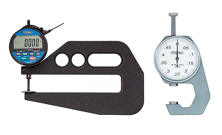
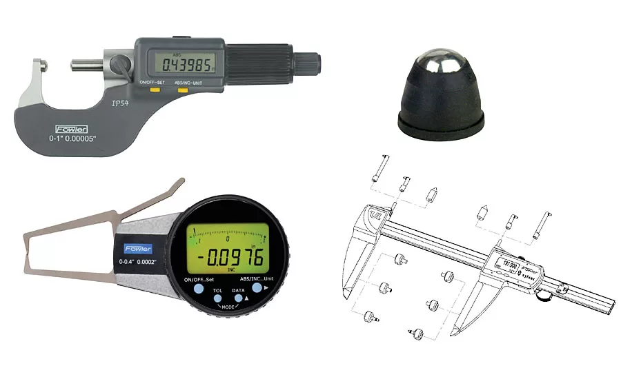
On the surface, thickness seems like an easy measurement to take, as dimensional measurements go. You have two big, flat, parallel planes on which to plant your gage. For hard materials, like metal sheet, you can use three of the four measuring capabilities of a slide caliper. A micrometer does very nicely, too, if you have the time and need the accuracy. If the need is constant, then speed becomes a consideration. In this case, dedicated thickness gages exist, which are fast, simple, and spring-loaded to make the measuring force repeatable.
What if the material is irregular?
Non-flat materials can be checked with much the same methods. All this requires is a spherical or conical contact point for your gage. Dedicated gages are available, as are add-ons for most common gages.
What if we need to take a measurement in the middle of a sheet?
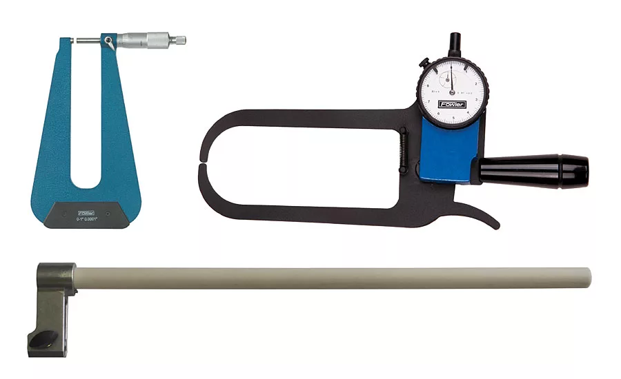
This is a little tougher. Specialty deep frame micrometers and external caliper gages exist which can reach much farther onto a thin workpiece than standard tools allow. Sometimes, a drop indicator is employed with a long reach holder to do the job. More sophisticated applications may use a separate indicator up through the table and use a differential reading to eliminate error from bowing of the material. A height gage with long reach attachments may also be a good solution.
How about a tube wall?
This is a little trickier. You can use a micrometer with a ball anvil on the inside. There are specialty micrometers which use a pin for the fixed contact to allow access into very small tubes. External caliper gages also exist for this purpose. In each case, the inside contact must be rounded more sharply than the tube, to ensure a single point of contact for the measurement.
What if the material is soft or flexible?
For this type of application it is critical to ensure that your measuring pressure is correct and repeatable. Your baseline thickness reading won’t match any subsequent readings if the material is deforming differently each time. Measuring pressure is a function of two things: the force and the area.
For measurements of this type, a drop indicator in a measuring stand is the way to go.
The force is set and very repeatable. If an extra light touch or linearity is required, the spring can be removed and weights used to provide the force. Weights can be mounted to the top of the slide in place of the lifting handle.
The area can be adjusted by way of the contact point. Innumerable flat and spherical contact points of all sizes and shapes are available. The only catch is to know whether your contact point uses inch (4-48) or metric (M2.5) thread. There are only these two common options.
This link describes the four ways. Click here to view it.
Coating thickness
Prior to this, the discussion has assumed that the user has access to both faces of the material in question. In the realm of coatings, this is not the case. Sure, you can destroy a spot of the coating and take a depth measurement to the substrate below, but this is archaic. Let’s use science instead!
There are three basic working principles for coating thickness gages. The substrate material is the deciding factor in which type of gage to utilize.
Magnetism
This type of coating thickness gage requires that the substrate be ferrous and have something to say to a magnet. The coating must not be magnetic. The concept is simple, the thickness of the coat directly affects the strength of the attraction between the magnet and the substrate. The closer they are, the stronger the pull. Gages exist which use permanent and electric magnets.
Eddy Current
Conductive materials with non-conductive coatings may be measured using the hall effect. The concept is much the same as the method above, except that a magnetic field must be induced in the substrate using a high frequency alternating current electromagnet. The resultant induced current creates its own magnetic field which may be measured. Again, coating thickness directly affects the strength of this field.
Ultrasonic
For materials which refuse to cooperate with the methods above, sound may be used to gage distances. Sound waves will reflect from a boundary layer between two dissimilar materials. A sensor producing and sensing sound waves with a short enough wavelength can use this tiny sonar to gage distance. The distance here is the thickness of the coating. This method is susceptible to errors which stem from the density of the material being measured. I have found that proper calibration to the material is critical when using a gage build on this principle.
Whatever your material or its position, if it has a thickness, sophisticated tools exist to measure it.
Looking for a reprint of this article?
From high-res PDFs to custom plaques, order your copy today!


