Coating Thickness Basics
Electronic coating thickness gages operate on the magnetic induction or the magneto static principle for measuring coatings applied over ferrous substrates. Regardless of the measuring principle, certain manufacturer-prescribed procedures must be followed to ensure the gage is operating at optimal performance. In fact, if these procedures are not followed, the measurement results could greatly mislead the assessment of the coating thickness.
As the manufacturing sector begins to heal, activities will come alive-but perhaps not by those same acquaintances. The old phrase lean and mean will probably take effect. To that end, the person charged with testing coating thickness may be less familiar with the task at this time than his predecessors. For that reason it is appropriate to revisit some of the basics of coating thickness measurement.
Electronic coating thickness gages operate on the magnetic induction or the magneto static principle for measuring coatings applied over ferrous substrates. For coatings applied on nonferrous substrates, the eddy current principle is typically used.
Regardless of the measuring principle, certain manufacturer-prescribed procedures must be followed to ensure the gage is operating at optimal performance. In fact, if these procedures are not followed, the measurement results could greatly mislead the assessment of the coating thickness.
These control standards should have a stated known thickness with a tolerance statement. If the operator is placing the control standard over a concave or convex surface, he should ensure that there are no air gaps-these will play into the reading generated by the device and overstate the reading. As with any measuring task, care should be extended to ensure the operator does not introduce variables into the process.
Take several readings and compare the output of the gage to the stated value, taking into consideration the control standards tolerance statement as well as the gage’s tolerance statement. If the readings fall within the acceptance range, then it is acceptable to assume the gage is operating properly and the subsequent readings can be relied on. If not, operators will need to follow the gage manufacturer’s procedure in order to correct the situation.
If, after carefully following the gage manufacturer’s instructions for gage optimization the results are still outside the acceptance range of the control standard, there are some points to consider before sending the gage out for service.
Another possible cause for a gage to produce out-of-tolerance measurements could be probe placement. It is important that the probe meets the surface in a perpendicular fashion.
Many probes have spring-loaded housings that serve the purpose of applying the same amount of surface pressure from one measurement to the next. However, the tip of the housing could become worn from use. Extreme heat over time also could change the contact surface and, as a result, not allow the probe to meet the surface in a perpendicular fashion as it once did. If this seems to be the case, the operator has no choice but to have it serviced.
Some manufacturers have addressed that by incorporating the processing in the probe at the point of measurement, illuminating the potential influences of electromagnetic interferences. If one suspects this might be happening, simply move to an interference-free area. If this clears up the issue, the out-of- tolerance measurements could be attributed to electromagnetic interference. If not, more than likely something else is contributing to the situation. Worn internal wires might be the cause; however, resolution to this is in the hands of the service department.
With nonferrous and alloy substrates, operators sometimes might generate a measurement that seems to be way off while surrounding measurements appear to be in line. If it is an alloy, it could be that they have located a nonhomogenously dispersed area. In this area, the zero reference point changes.
To clarify matters, an alloy is comprised of two or more metals. They are combined for various reasons but regardless, they are combined much like ingredients of a cake: in order for the outcome to be acceptable, the ingredients need to be mixed well. Sometimes they are not and concentrations of one ingredient are more prevalent in an area.
What happens in these cases is that when operators set the zero reference point, that zero is based on the homogenously dispersed properties of the surface on which the operators take the reference measurement. The accuracy and reliability of subsequent readings are predicated on the consistency of all factors taken into consideration when the gage was optimized. Any change will affect the measurement. So when operators measure over these areas of nonhomogenously dispersed alloys, the zero reference is affected and causes a skew in gage output.
When the situation just described occurs, there is nothing to be concerned about with regard to the gage. The gage is reacting as would be expected given the situation. However, the question becomes how to assess the true thickness of the coating at this location. The only way would be to do a destructive test using a device that cuts into the coating down to the substrate and allows optical inspection. These devices are available, but they are destructive to the coating.
This covers only the very basics of coating thickness testing and at the broadest scale possible. They apply regardless of the application and are often overlooked.
Coating thickness gages have come a long way and are much easier to use than what was available years ago. However, with simplicity sometimes certain important factors can be overlooked. Those new to using coating thickness testing gages can easily fall victim to producing erroneous measurements simply by being unaware of some simple factors.
What is the biggest problem with a coating thickness testing gage? They most always will give operators a result, and will display a value. That is why it is important to take into consideration the points mentioned and properly optimize and verify the coating thickness gage is operating correctly. Q
“Coating Thickness Gages: A Fast Evolution”
“Measure Coating Thickness”
First, inspect the sensor tip to make sure nothing has transferred to it and make sure the control standard and specimen surface are clean.
Particles in the air, oils from handling the objects measured or the transfer of the coating itself to the gage sensor all can contribute to the gage output.
Be sure to inspect the gage sensor and the surfaces that will be measured.
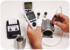
Independent of the brand used, it is important to always assess the gage’s performance prior to relying on any results generated from the gage. Source: ElektroPhysik
As the manufacturing sector begins to heal, activities will come alive-but perhaps not by those same acquaintances. The old phrase lean and mean will probably take effect. To that end, the person charged with testing coating thickness may be less familiar with the task at this time than his predecessors. For that reason it is appropriate to revisit some of the basics of coating thickness measurement.
Electronic coating thickness gages operate on the magnetic induction or the magneto static principle for measuring coatings applied over ferrous substrates. For coatings applied on nonferrous substrates, the eddy current principle is typically used.
Regardless of the measuring principle, certain manufacturer-prescribed procedures must be followed to ensure the gage is operating at optimal performance. In fact, if these procedures are not followed, the measurement results could greatly mislead the assessment of the coating thickness.
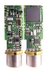
This coating thickness testing probe with sensor-integrated digital signal processing technology is shown with the probe housing removed. Components that are typically located in the host gage are housed in the probe itself, and the complete coating thickness processing takes place in the probe at the point of measurement, at the time of measurement, making it virtually immune to any electrical interference as might be the case with conventional analog signal processing. Source: ElektroPhysik
Procedures
Independent of the brand used, it is important to always assess the gage’s performance prior to relying on any results generated from the gage. It is an easy task and does not require much time. Most, if not all, gage manufacturers supply control standards for this purpose. With electronic gages it is best to use flexible Mylar-type control standards, unless the surface area is flat, in which case a bonded coating is preferred provided it is applied to the same substrate as the application. This way they can be placed over an uncoated specimen. This ensures the operator is replicating the same application that they will be measuring after the actual coating is applied.These control standards should have a stated known thickness with a tolerance statement. If the operator is placing the control standard over a concave or convex surface, he should ensure that there are no air gaps-these will play into the reading generated by the device and overstate the reading. As with any measuring task, care should be extended to ensure the operator does not introduce variables into the process.
Take several readings and compare the output of the gage to the stated value, taking into consideration the control standards tolerance statement as well as the gage’s tolerance statement. If the readings fall within the acceptance range, then it is acceptable to assume the gage is operating properly and the subsequent readings can be relied on. If not, operators will need to follow the gage manufacturer’s procedure in order to correct the situation.
If, after carefully following the gage manufacturer’s instructions for gage optimization the results are still outside the acceptance range of the control standard, there are some points to consider before sending the gage out for service.
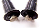
Before sending the gage out for service, inspect the sensor tip to ensure nothing has transferred to it, and make sure the control standard and specimen surface are clean. Source: ElektroPhysik
Considerations
First, inspect the sensor tip to ensure nothing has transferred to it. Also, make sure the control standard and specimen surface are clean. This factor alone contributes to more misassessments of coating thickness readings than any other factor. Keep in mind that the thickness dimensions of coatings dealt with here are very small relative to what operators are otherwise used to. Particles in the air, oils from handling the objects measured or the transfer of the coating itself to the gage sensor can contribute to the gage output. So as a first measure, be sure to inspect the gage sensor and the surfaces that will be measured.Another possible cause for a gage to produce out-of-tolerance measurements could be probe placement. It is important that the probe meets the surface in a perpendicular fashion.
Many probes have spring-loaded housings that serve the purpose of applying the same amount of surface pressure from one measurement to the next. However, the tip of the housing could become worn from use. Extreme heat over time also could change the contact surface and, as a result, not allow the probe to meet the surface in a perpendicular fashion as it once did. If this seems to be the case, the operator has no choice but to have it serviced.
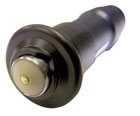
Electronic coating thickness gages operate on the magnetic induction or the magneto static principle for measuring coatings applied over ferrous substrates. Source: ElektroPhysik
Electromagnetic Fields
Strong and even some weaker electromagnetic fields can affect measurements. Most devices generate an analog signal at the probe and send that signal to the gage for processing. Along the way electromagnetic fields can affect that signal before it arrives at the microprocessor for processing into a unit of measurement that operators can understand.Some manufacturers have addressed that by incorporating the processing in the probe at the point of measurement, illuminating the potential influences of electromagnetic interferences. If one suspects this might be happening, simply move to an interference-free area. If this clears up the issue, the out-of- tolerance measurements could be attributed to electromagnetic interference. If not, more than likely something else is contributing to the situation. Worn internal wires might be the cause; however, resolution to this is in the hands of the service department.
With nonferrous and alloy substrates, operators sometimes might generate a measurement that seems to be way off while surrounding measurements appear to be in line. If it is an alloy, it could be that they have located a nonhomogenously dispersed area. In this area, the zero reference point changes.
To clarify matters, an alloy is comprised of two or more metals. They are combined for various reasons but regardless, they are combined much like ingredients of a cake: in order for the outcome to be acceptable, the ingredients need to be mixed well. Sometimes they are not and concentrations of one ingredient are more prevalent in an area.
What happens in these cases is that when operators set the zero reference point, that zero is based on the homogenously dispersed properties of the surface on which the operators take the reference measurement. The accuracy and reliability of subsequent readings are predicated on the consistency of all factors taken into consideration when the gage was optimized. Any change will affect the measurement. So when operators measure over these areas of nonhomogenously dispersed alloys, the zero reference is affected and causes a skew in gage output.
When the situation just described occurs, there is nothing to be concerned about with regard to the gage. The gage is reacting as would be expected given the situation. However, the question becomes how to assess the true thickness of the coating at this location. The only way would be to do a destructive test using a device that cuts into the coating down to the substrate and allows optical inspection. These devices are available, but they are destructive to the coating.
This covers only the very basics of coating thickness testing and at the broadest scale possible. They apply regardless of the application and are often overlooked.
Coating thickness gages have come a long way and are much easier to use than what was available years ago. However, with simplicity sometimes certain important factors can be overlooked. Those new to using coating thickness testing gages can easily fall victim to producing erroneous measurements simply by being unaware of some simple factors.
What is the biggest problem with a coating thickness testing gage? They most always will give operators a result, and will display a value. That is why it is important to take into consideration the points mentioned and properly optimize and verify the coating thickness gage is operating correctly. Q
Quality Online
For more information on coating thickness measurement, visit www.qualitymag.com to read the following:“Coating Thickness Gages: A Fast Evolution”
“Measure Coating Thickness”
Tech Tips
Consider these points before sending the gage out for service:Looking for a reprint of this article?
From high-res PDFs to custom plaques, order your copy today!


