Who’s the Keeper of GD&T Data?
GD&T is widely considered to be an essential tool for communicating design intent and ensuring parts meet the desired form, fit, function and assembly.

This software provides real-time color coded inspection feedback tied directly to intelligent GD&T definitions. Red – out of tolerance, high; Green – in tolerance; Blue – out of tolerance, low. Source: Verisurf
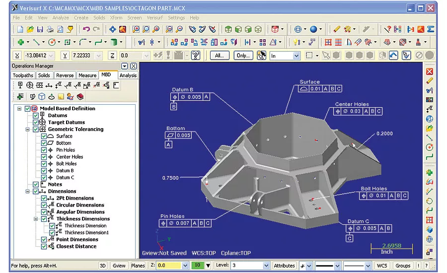
If your inspection software is based on a 3D CAD platform, you can import Intelligent GD&T data directly along with the 3D model. Source: Verisurf
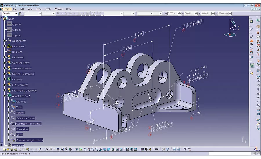
Computer Aided Design (CAD) - Dassault Systems CATIA model with GD&T annotations and inspection balloons generated with Inceptra MBD Accelerator. Image courtesy of Inceptra
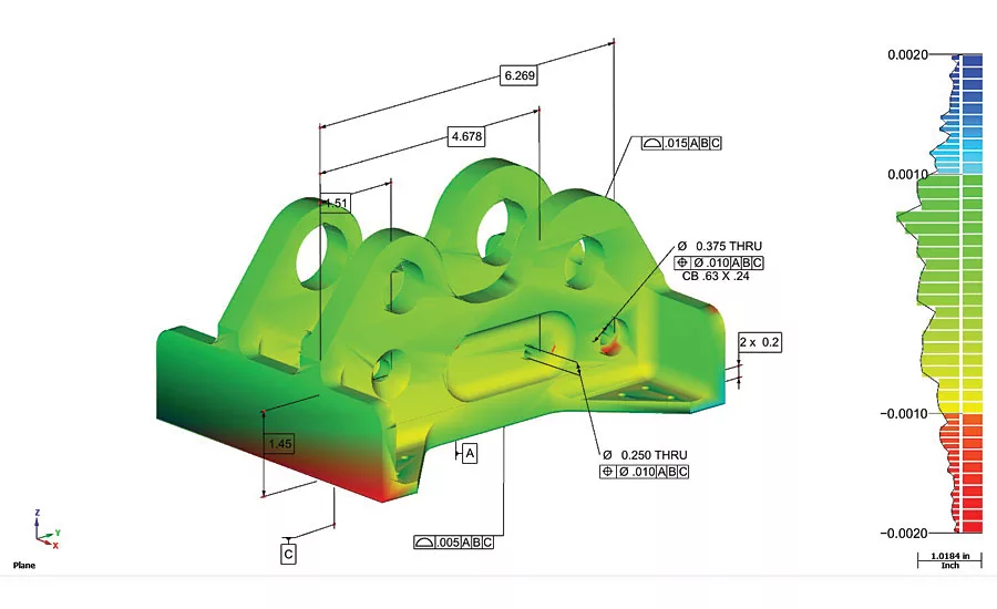
Computer Aided Inspection (CAI) – Verisurf MBD inspection software analyzes point cloud to CAD model nominal and displays deviation color map. Green is in tolerance. Blue is out of tolerance out of the part. Red is out of tolerance into the part. Source: Verisurf
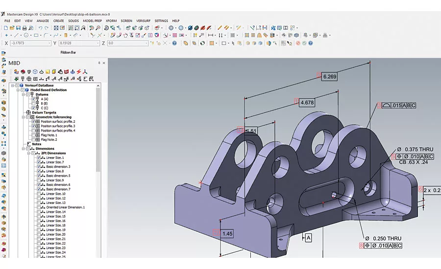
Computer Aided Manufacturing (CAM) – Mastercam CNC machine programming software with optional CATIA MBD imports CAD with model associative GD&T. Imported GD&T annotations can be edited and additional annotations added as part of the manufacturing engineering process. Source: Verisurf
Who’s the keeper of GD&T data?
- Design engineering
- Architectural engineering
- Civil engineering
- Electrical engineering
- Industrial engineering
- Mechanical engineering
- Manufacturing engineering
- Tool engineering
- Quality engineering
In today’s highly specialized world of engineering it takes a village to develop and produce a component part, let alone a complete product. Who is responsible for Geometric Dimensioning and Tolerancing (GD&T) data? The answer depends on many variables, including the type of part or product being produced, production methods, critical specifications and design variables.
Ultimately, it is everyone’s responsibility to know and have access to critical GD&T data associated with their respective role in the manufacturing process. When necessary GD&T data is missing there must be a way to introduce the missing data and keep the process moving forward, while maintaining the integrity of the design intent and data authority.
TECH TIPS
|
GD&T is a universal design language that has been rigorously studied and applied by manufacturers around the world and is widely considered to be an essential tool for communicating design intent, ensuring parts meet the desired form, fit, function and assembly. It includes important changes addressing the concept of feature design, datum references and degrees of freedom, surface boundaries and axis methods of interpretation, profile tolerances, symbology and modifiers tools.
A CASE FOR MODEL-BASED DEFINITION
The central concept behind model-based definition (MBD) is that the digital model contains all of the detailed information necessary to produce and reproduce a part. This includes everything from design and manufacturing to quality inspection. Today, most CAD design is done in 3D; if managed properly using MBD the 3D CAD model will continue to have GD&T value added to it throughout the design, manufacturing and inspection processes. In the end the MBD CAD model will be the design authority, containing all data to reproduce the part, through inspection. That’s right, when employing an MBD strategy the Golden Part becomes virtual.
It’s nice to think that everything can be planned for and anticipated in the design phase of a project, but that’s just not realistic. To simplify the manufacturing process and give examples of GD&T data in an MBD environment, we look at the whole in terms of design, manufacturing and inspection.
DESIGN ENGINEERING
Quite often, approved product designs lack necessary detail for manufacturability. Critical overall tolerances are usually indicated, but typically supporting specifications must be further defined as intelligent annotations. There are two formats of GD&T definition data. Although both are labeled “3D annotation,” one format is purely for display; the other feeds downstream applications. Presentation is the display only format for GD&T. While the tolerancing may be associated to the model, the information is just text. There is no intelligence behind the 3D annotation. As a result, the GD&T data must be interpreted. The presentation format is similar to typing a mathematical equation in Microsoft Word. It conveys information, but the computer cannot use it in a calculation. This type of GD&T data is commonly referred to as “decorating the model.”
MANUFACTURING ENGINEERING
Considerable intelligence and value can be added to the MBD CAD model authority during manufacturing engineering, depending on intended processes and equipment being used. When producing legacy parts, for example, in support of Maintenance Repair and Overhaul (MRO), CAD data is not always available. Often in these situations a capable CAD based reverse engineering application can be used to reverse engineer missing features back into 3D CAD while providing important GD&T data to support manufacturing and downstream inspection. This same process can be used to geometrically define a complex surface profile.
QUALITY ENGINEERING
If your inspection software is based on a 3D CAD platform, you can import Intelligent GD&T data directly along with the 3D CAD model. In the case of presentation annotations, the quality or manufacturing engineer can determine which are relevant and simply add the GD&T specifications to the 3D CAD model when developing the inspection plan.
When the information is imported from the native CAD system as a GD&T representation, there is a true MBD implementation. The authority of the dataset is preserved. The same is true if GD&T display data (presentation) is imported directly or via STEP translation and then entered into the inspection application.
MAINTAINING A DIGITAL THREAD
This refers to the use of intelligent 3D models to electronically exchange and process product and manufacturing information all the way from design through inspection of the final part, a tightly integrated, seamless string of activities that manufacturers are calling a “digital thread.”
Modern manufacturing is rapidly adopting model-based definition (MBD). When employing an MBD strategy, the CAD model with annotated GD&T data becomes more than the nominal to which all parts are measured and inspected against. MBD keeps the all-important digital thread intact—from design to reverse engineering (if necessary), to manufacturing, inspection and quality reporting.
In order to accomplish this effectively all downstream software must be rooted in CAD and have the ability to import from, manipulate, annotate, model, inspect against, and export back to virtually any CAD file format. At the end of the day it is the job of inspection software to align and compare the nominal CAD model to the finished part.
Just as most companies standardize on a CAD/CAM platform, they should also try to standardize on an inspection and reverse engineering software that will best support their manufacturing enterprise. This will ensure consistency of operation, quality reporting, data management, and reduced training and support costs. Be sure the inspection and reverse engineering software you select is open and offers the necessary level of interoperability to support your current and future manufacturing inspection requirements:
- Is the inspection software based on a CAD platform, including 3D modeling?
- Does it import and export all CAD files and models seamlessly?
- Will it import and allow annotation of GD&T data?
- Does it accept measurement data from all digital measuring devices?
- Is the software capable of controlling all digital measuring devices?
- Does it have the flexibility and embedded tools to handle the range of inspection data, from manual contact probing to noncontact point clouds?
It is the responsibility of collective engineering to utilize, observe and maintain GD&T data throughout all aspects of design, manufacturing and inspection in order to insure original design intent—all while maintaining the digital thread.
Looking for a reprint of this article?
From high-res PDFs to custom plaques, order your copy today!


