Tolerancing Standards: A Comparison
As we consider the possibility that products can be manufactured anywhere in the world, we must also think about the specifics of the standard we use to describe the product requirements.

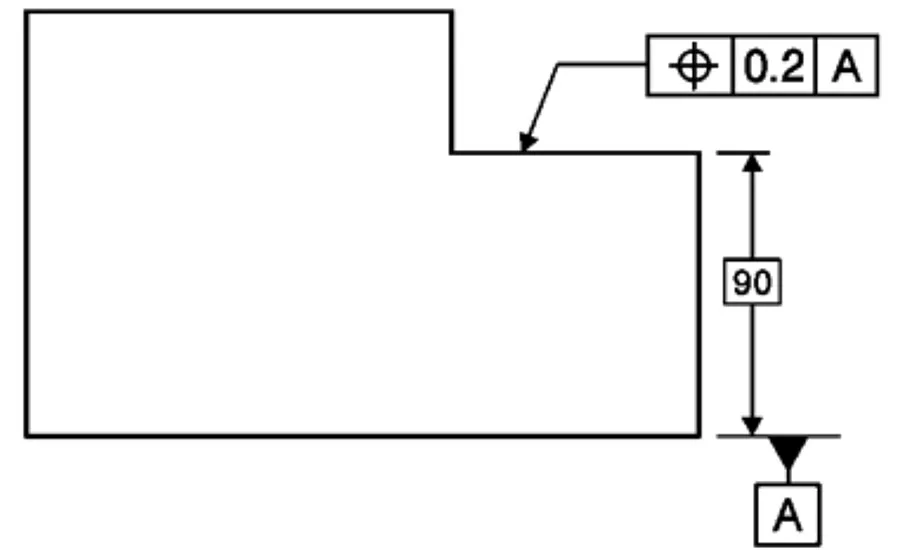
Figure 1: Use of a position tolerance permitted by ISO, but not ASME standards
Much has been written about the advantages of Geometric Dimensioning and Tolerancing (GD&T), and much of it is true. By explicitly describing datum systems and zones to control the allowable variability of the part characteristics, many of the ambiguities that arise from limit tolerances on dimensions are overcome. GD&T has been growing steadily in acceptance since its introduction in the 1950s with MILSTD8 (actually, the Ordnance Corps ORD 30-1-7 appeared in 1946, and also described dimensioning and tolerancing). One of the benefits of GD&T is that the requirements are captured in symbols, rather than notes, so a design can be manufactured to the specifications regardless of the native language at the manufacturing facility. As we consider the possibility that products can be manufactured anywhere in the world, we must also think about the specifics of the standard we use to describe the product requirements.
The current ASME standard for GD&T is ASME Y14.5-2009; this standard is developed by subcommittee 5 of the ASME standards committee Y14 Engineering Product Definition and Related Documentation Practices. The Y14.5 standard enjoys a large circulation and sales worldwide, so it can truly be thought of in international terms. However, there are other standards for GD&T, specifically those produced by ISO technical committee 213 Dimensional and geometrical product specifications and verification. How can we be sure that the manufacturer of our product will have sufficient training in the ASME GD&T? If we are part of an international company, will all of our sites be using the same standards for GD&T when they develop designs or produce products? And finally, are the ASME and ISO standards really that different anyway?
TECH TIPS
|
This article is intended to provide the reader with information about the differences between the US National (ASME/ANSI) tolerancing standards and the international (ISO) tolerancing standards. This information may be used in determining a long-term strategy for the implementation of these standards in the reader’s company, and also in identifying areas where a corporate standard may be needed to clarify the intent of the designers within that company.
INTRODUCTION
There are many technical differences between the ASME and ISO tolerancing standards. This article will not focus on these differences as much as the structural and organizational differences that might influence a company to choose one set of standards over the other. A simple example, shown in Figure 1, shows an instance of how the standards differ. The location of a surface is being controlled relative to a datum feature A. The notation shown in the figure is permitted by the ISO standards, in that the position of the surface is controlled relative to the datum feature. In ASME Y14.5 standards, the use of the position tolerance is reserved for features of size (spheres, cylinders, and opposing pairs of planes) and some profile features. The single plane is not a feature of size, and so a position tolerance may not be used. However, the same control is available using the surface profile tolerance.
While there are many such differences between the current standards, there is nothing—of which I’m aware—that would prevent a designer from being able to specify exactly what they want. The primary differences are in the default meaning of certain symbols (which can always be over-ridden with a symbol or note).
Furthermore, I believe that more errors are made by designers not understanding the full implication of the tolerances that they specify than by designers confusing the use of ISO versus ASME tolerancing standards. In the shorter term, the choice between ISO and ASME may be less important than adequate training for designers so that they can ‘encode’ their criteria in a drawing or model, and training for inspectors so that they can ‘decode’ the meaning of the drawing or model.
MAJOR DIFFERENCES
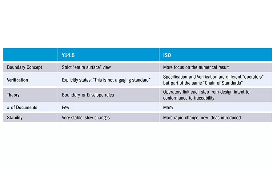
The major differences between the ASME and ISO tolerancing standards have been classified in the five categories that follow.
1. Boundary concept
The Y14.5 standard has always considered the control of all points on the surface of a feature. By extension, the ‘mating size’ concept is used to describe the size of a feature, meaning every point on the surface of a feature must fit within a boundary having the specified size. For example, if the diameter specification for a cylindrical pin is 10.0 ± 0.1, the entire pin must fit inside a theoretically perfect cylindrical shell of diameter 10.1.
Alternatively, the ISO standards consider the least squares size of a feature as the default. This means that some of the points might lie outside of a boundary that is defined by the size specification, while still conforming to the size specification. For the same size specification as above (10.0 ± 0.1), a pin whose least-squares size is 10.1 would conform to the specification although points on the surface could exceed the perfect boundary of diameter 10.1.
An added fly in the ASME ointment is that the Y14.5.1-1994 standard (mathematical principles of GD&T) states that ‘all points on the surface’ refers to the points after some sort of smoothing operation. This is necessary because the idea of a point on the surface of a part is somewhat nebulous when we consider atomic-level models, and we have to make some assumptions about what the surface actually is. While the reasoning behind the smoothing is sensible, there is some disagreement within the standards committees as to what method of smoothing is required, or permitted.
The ISO standards specifically rely on a filtering operation in the modeling of the surface.
2. Specification vs. Verification
The ASME standard intentionally distances itself from Verification (measurement / gaging). In clause 1.1.6 of ASME Y14.5-2009, the standard states “This document is not intended as a gaging standard. Any reference to gaging is included for explanatory purposes only. For gaging principles see ASME Y14.43 Dimensioning and Tolerancing Principles for Gages and Fixtures.” In other words, the ASME standard describes acceptable geometry of a part, not how the part might be measured.
The ISO standards express a duality between specification and verification. Whatever is done in the specification process is mirrored in the actual measurement process. This is described as the “duality principle” and ISO tolerancing standards are part of a “chain of standards” linking the designer’s intent with the definition of the meter in the SI.
Link A: Symbols and indications
Link B: Feature requirements
Link C: Feature properties
Link D: Conformance and
non-conformance
Link E: Measurement
Link F: Measurement equipment
Link G: Calibration
The ASME mindset reflects a well thought-out principle that the designer may not care how the part is inspected, but only cares about the part geometry. This is not contradicted in the ISO standards, but the ISO standards do represent a more direct recognition of the links between design and verification.
3. Underlying Theory
The ASME standard is based on the idea of specifying geometrically perfect zones within which the feature surfaces must lie. This is often referred to as a preference for “hard gaging,” as often gages can be built that are a physical representation of the tolerance zones. A good example of this is the cylindrical mating envelope described in the boundary concept section.
The ISO standards introduce a series of operators that take the user from the specification to extraction of points from the part surface to calculation of values that are compared to the tolerances. Because of this calculation element, the standards are often thought of as “CMM Friendly.”
While these are different approaches to tolerancing, the designer can explicitly specify a meaning different from the default of that standard in use. For example, the designer can specify the envelope principle for size evaluation by putting the appropriate symbol (a circled E) next to the specification, or in the default tolerance block.
4. Number of Standards documents
The ASME standards are primarily the Y14.5 standard, supported by others: Y14.5.1 (mathematical principles); Y14.8 (castings); Y14.41 (CAD representation); Y14.43 (functional gages). Additional standards are being developed that cover the reporting of measurement results (Y14.45).
The ISO standards include different documents for all aspects of tolerancing: geometrical tolerances, datums, size, as well as separate standards for various tolerancing theories. A partial list includes:
ISO 286 – limits and fits
ISO 1101 – form, orientation,
location, and runout
ISO 1119 – series of conical tapers
ISO 1660 – profiles
ISO 3040 – cones
ISO 5458 – position
ISO 5459 – datums
ISO 14405 – size
Note that many of these standards have multiple parts. For example, ISO 14405-1 (linear sizes), ISO 14405-2 (dimensions other than linear sizes), and ISO 14405-3 (angular sizes – under development) describe the size of different types of features.
With the many different ISO standards available, it is sometimes hard to determine which standard is appropriate (cones or conical tapers?) or which standard takes precedent if there is an inconsistency between two different ISO standards.
5. Stability
The ASME tolerancing standard Y14.5 emerged in 1957 as an ASA standard, and has been revised, on average, every 10 years or so. The pace of change is quite slow, and much negotiation is required to introduce new concepts or notation.
By contrast, the ISO documents can change more quickly as they each focus on a narrower area of the entire tolerancing spectrum. This allows more responsive changes when improvements are sought in a specific area, but makes the application of consistent changes across all of the standards difficult.
SUMMARY AND CONCLUSION
The table summarizes the differences described in this article. Each of these differences can be viewed as favoring one standard over the other, and I would like to emphasize again that the adequate training of personnel is of great importance. As I expect many organizations, particularly international companies, have legacy drawings that reflect both standards, the understanding of the differences is equal in importance (in the short term) to the choice of standards for future documents.
Looking for a reprint of this article?
From high-res PDFs to custom plaques, order your copy today!


