Deploying a Vision System
Integration, adaptation and coexistence are vital for successful vision system deployment.
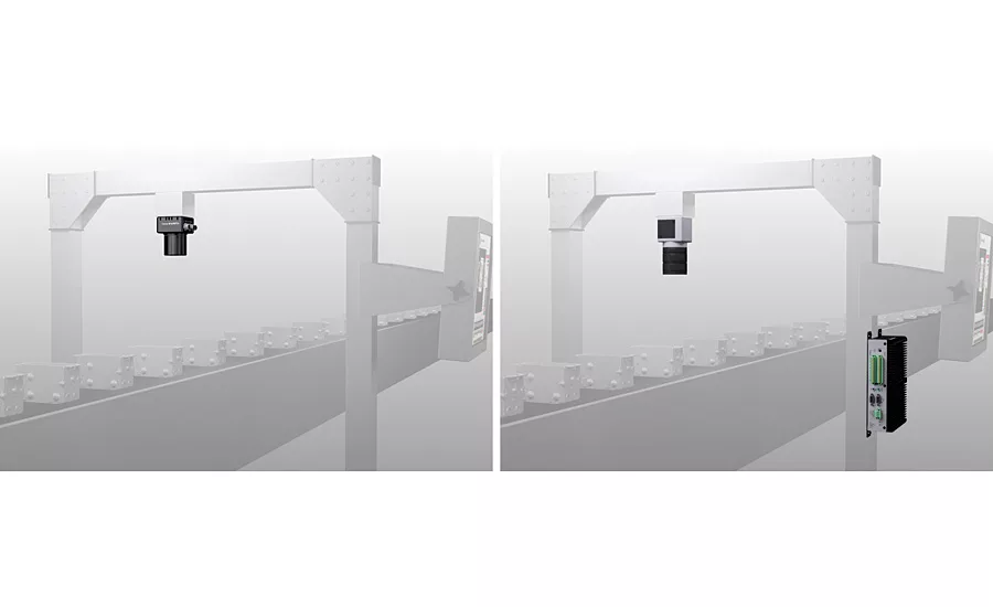
Figure 1: Smart camera or PC based vision system with common vision software. Source: Matrox Imaging
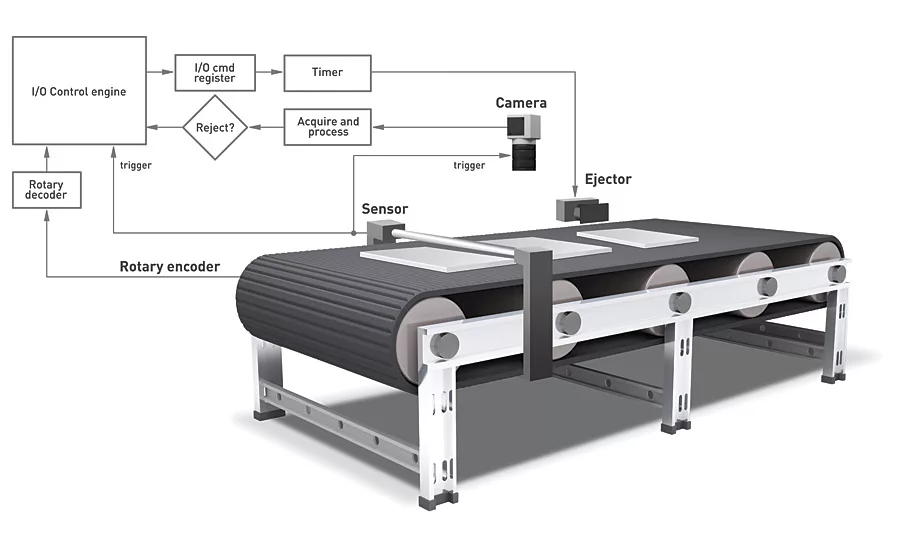
Figure 2: Typical system with real time IO control. Source: Matrox Imaging
Vision systems play a critical role in factory automation. They guide, inspect and track product manufacturing, assembly and packaging to meet today’s quality standards. But vision systems are not an end unto themselves as a production line, cell or machine’s purpose is first and foremost to manufacture, assemble and package products. Being a small cog in a big wheel, vision systems must coexist and fit in with other indispensable and often already-present and proven automation processes and equipment. It is more practical to make changes to the vision system rather than changing the whole production line.
Today, it is necessary for vision systems to provide capabilities beyond image capture and analysis to integrate as tightly and seamlessly as possible with established automation processes and equipment. They must respond to external requests as well as provide results and/or output actions externally in a timely fashion. Another important consideration is that vision systems should not adversely affect the overall production speed. They must be capable of integrating without slowing down the existing production line.
The above mentioned requirements determine the type of vision system that is needed for a particular job. As a recent trend, some smart cameras available in the market today are designed with features to easily emulate and thus replace PLCs in smaller scale, simpler installations. They are more self-contained for easier procurement, installation and servicing. When allocated spaces for vision systems are small, smart cameras that generally have a tiny footprint are a good fit. The smart camera should be physically able to withstand the physical conditions on a line or within a cell. For tough and humid conditions, an IP-67 rated housing and M12 connectors ensure dust-proof, immersion-resistant and rugged performance.
When more computing power is needed to keep up with higher production rates, a vision controller or a PC-based solution with separate camera(s) may be the recommended way to go, even though recent smart cameras themselves come with good processors capable of handling most vision applications. For example, smart cameras with recent Intel embedded processors allow inspections to take place on fast moving lines or perform more inspections in the allotted time.
Whether your hardware platform is a smart camera, vision controller or PC-based solution with cameras, the underlying common need is vision software. (See Figure 1.) Integrated development environments (IDEs) are available that are straightforward to use, for example with intuitive flowchart-based methodology, for easier access to and faster vision application development. IDEs covering all aspects of a vision application are obtainable: from image capture, analysis and synchronization to interaction with external automation equipment, enterprise systems and operator interface.
INTEGRATION WITH PLCS AND HMI PANELS
Programmable logic or automation controllers (PLCs or PACs) are the primary conductors for the larger and more complex production cells and lines. They monitor, coordinate and perform activities through the various sensors and devices that connect to them. A vision system is but one of many such devices and sensors. A vision system interacts with a PLC most often through an Ethernet-based industrial communication protocol. The most commonly encountered protocols are EtherNet/IP and PROFINET.
Not only must a vision system support these protocols, it should also adapt itself to their usage. It has to work with the pre-existing finely-tuned PLC timing diagrams and logic. It must interact using already-established PLC data tables. Communication with a vision system represents but a very small part of a PLC’s job.
PROFINET imposes yet another requirement for a vision system. An IO cycle time is established when a master device (PLC) and slave devices (example, vision system) connect together. Devices must regularly produce something over the link within this cycle time (plus a minimal grace period). Slave devices failing to produce within the cycle time leads to an error, which suspends all other operations on the master device, which in turn halts the production cell or line. A pure software implementation of the PROFINET protocol running on an operating system like Windows cannot ensure production within this cycle time. The cycle time could be extended in this case but at the cost of increased latency, which adversely affects overall performance. A hardware-assisted PROFINET implementation ensures the necessary production within an optimal IO cycle time.
Production cells and lines commonly use dedicated HMI panels to communicate status and results as well as accept adjustments and control from human operators. These often pre-existing operator interfaces cover all aspects of a given production cell or line. Therefore, the view into a vision system program must be part of, and not separate from, the overall operator interface. This requires the vision system to be able to publish status and results, and accept adjustments and control from such external operator interfaces.
INTERACTION THROUGH DISCRETE IOS
A vision system with proper discrete IOs can handle the tasks necessary for tending to simpler production processes. This approach, if workable, can result in substantial cost savings by eliminating the need for a PLC. The vision system’s discrete inputs must be able to catch and store successive external events while waiting for the main program to get to them for processing. The vision system’s outputs must be able to be set at specific times and for specific durations based on either relative (example, encoder pulses) or absolute time bases. A hardware-assisted implementation of these discrete inputs and outputs ensures that the above capabilities are delivered. (See Figure 2.)
An example of such hardware-assisted implementation is a vision system used by a major device manufacturer for inspecting a high-value rod-like device. The rod-like device needed to be precisely rotated in smaller increments, up to 180 degrees, for a proper complete inspection. The rotations were done using a stepper motor, which was driven by pulses of specific duration from the vision system. Apart from the integrated motion control, other complex aspects to contend with in the project were contrast between surface and background being poor and having to take multiple measurements at known intervals. This manufacturer was able to save thousands of dollars by doing away with PLCs and also saved space and power supply.
CONCLUSION
There is more to deploying a vision system than image capture and analysis. Vision is an automation accessory that must integrate itself within a production process without adversely affecting the performance of the latter. A vision platform must also provide facilities to insert itself and interact with other, sometimes more central, automation equipment. V&S
Looking for a reprint of this article?
From high-res PDFs to custom plaques, order your copy today!


